
A machine has stopped in the middle of a job. The operator says it was “fine five minutes ago”. Production wants an answer straight away. Someone is already reaching for a relief valve, someone else wants to order a pump, and the fault still hasn't been defined properly.
That's where most wasted time starts.
A sound troubleshooting methodology isn't about slowing the job down. It's about stopping the wrong job from starting. In hydraulic work, that matters more than is generally acknowledged, because what looks like a fluid power fault often turns out to be somewhere else entirely. If you don't separate hydraulic, mechanical and electrical causes early, you can spend hours proving the wrong thing.
Preparation and Safety Before You Touch a Tool
When a hydraulic pack drops pressure or a cylinder stalls under load, the pressure to “just get into it” is immediate. Resist that. The first job is to make the machine safe and make the fault legible.
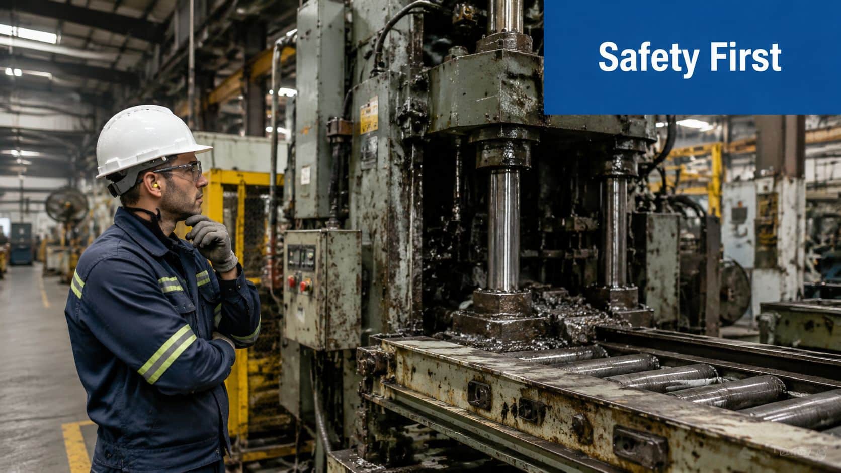
Start with isolation, not assumption
Hydraulic systems store energy even when the prime mover is off. Lock-out and tag-out has to cover electrical supply, stored hydraulic pressure, suspended loads and any mechanical movement that can drop, swing or creep. PPE matters as well. Gloves, eye protection and suitable clothing are basic. Face protection is sensible whenever there's a chance of atomised oil or a hose failure under pressure.
If the machine is in a dusty or demolition-heavy environment, contamination and site hazards overlap. Teams working around plant rooms, workshops or refurbishment areas should also learn about silica and asbestos risks before they treat the area as just another service call.
A lot of faults are made worse by starting cold checks too soon. Before disconnecting anything, confirm whether the symptom appeared at start-up, at operating temperature, under load, or during a particular movement. That affects everything that follows.
Practical rule: If the machine isn't safe, it isn't ready to diagnose.
Gather the baseline paperwork
The first tools aren't spanners. They're the circuit diagram, parts list, service history and operator account. A structured 13-step approach begins by gathering system documentation and a fluid sample before measuring temperature, pressure and flow under operating conditions, because you're trying to isolate root cause rather than chase symptoms through the circuit using a structured hydraulic troubleshooting sequence.
That paperwork tells you what the machine is supposed to do. Without that baseline, every reading is just a number with no context.
Use a quick pre-check like this:
- Find the schematic: Confirm pump type, relief arrangement, valve stack, actuator layout and any priority or flow divider functions.
- Read the history: Repeated hose failures, dirty return filters, slow cold starts and previous valve changes usually point somewhere.
- Check the fluid specification: Wrong grade oil creates false symptoms. If you need a refresher on ignition and handling concerns, review whether hydraulic fluid is flammable.
- Define the complaint exactly: “No power” is useless. “Boom raises unloaded but stalls halfway with load after warming up” is usable.
Without structure, initial diagnosis is poor far more often than technicians like to admit. The Hydraulic Troubleshooting Systematic Error Rate is approximately 85%, meaning nearly 9 out of 10 initial attempts miss the true root cause when there isn't a formal process in place according to this hydraulic troubleshooting reference.
That number reflects what happens in the field. People skip the setup, jump to the likely culprit, and then build a story around the first component they can reach.
Gathering Symptoms and Building a Theory
Good fault-finding starts with evidence you can see, hear and feel. Not guesses. Not favourite failures. Evidence.

Read the machine before you test it
A hydraulic system usually tells you quite a lot before a gauge goes on.
Look for external leaks, but don't stop there. Check rod condition, hose routing, rubbed looms, loose mountings, cracked brackets, milky oil, darkened oil, damaged couplings and any sign that a component has been changed recently. A shiny fitting in a dirty circuit often means someone has already been in there.
Listen next. Pump cavitation has a different sound from a relief valve passing oil. A bypassing valve can hiss. Mechanical binding often shows up as a labouring motor note or an uneven drive sound rather than a classic hydraulic whine.
Touch is useful, provided the system is safe to approach. A hot valve body beside a relatively cool line often points to internal leakage. A cold section in a live circuit can suggest no flow where there should be flow. Vibration matters too. A harsh buzz through a solenoid manifold feels different from chatter caused by unstable pressure.
Ask better questions
Operators usually know more than they first say. The problem is that many technicians ask poor questions.
Don't ask “what happened?” and leave it there. Ask:
- When did it first show up: Cold start, after warm-up, only under load, only on one function?
- What changed recently: New oil, filter change, hose burst, electrical work, a replaced coil, a recent knock?
- Is the fault constant or intermittent: Every cycle, every shift, only after extended running?
- Does anything still work normally: One service failing while others remain strong tells you a lot.
If your team uses a standard intake sheet, even a generic repair shop intake form can sharpen the initial fault report because it forces proper symptom capture instead of vague verbal handover.
The operator often gives you the first useful clue. The machine gives you the second. The gauges should confirm them, not replace them.
Use Five Whys properly
The Five Whys method is simple and still underused. In practice, you ask why repeatedly until the surface symptom gives way to the root cause. In maintenance work, that disciplined questioning can reduce repeat equipment failures by up to 35% because it pushes the team beyond symptom treatment when applied as a root-cause method in manufacturing maintenance.
A basic example:
-
Why is the actuator slow?
Because it isn't getting enough effective flow. -
Why isn't it getting enough effective flow?
Because oil is bypassing internally. -
Why is oil bypassing internally?
Because a valve spool is sticking off seat. -
Why is the spool sticking?
Because contamination is present in the circuit. -
Why is contamination present?
Because filtration control and fluid handling were poor after a recent hose failure.
At that point, replacing the valve alone isn't a fix. It's a pause before the same fault returns.
The aim here is to build a theory of probable cause. Not certainty yet. Just a theory strong enough to test in a sensible order.
Systematic Isolation Electrical Mechanical and Hydraulic
Most hydraulic troubleshooting guides start inside the hydraulic circuit. That's a mistake on mixed systems.
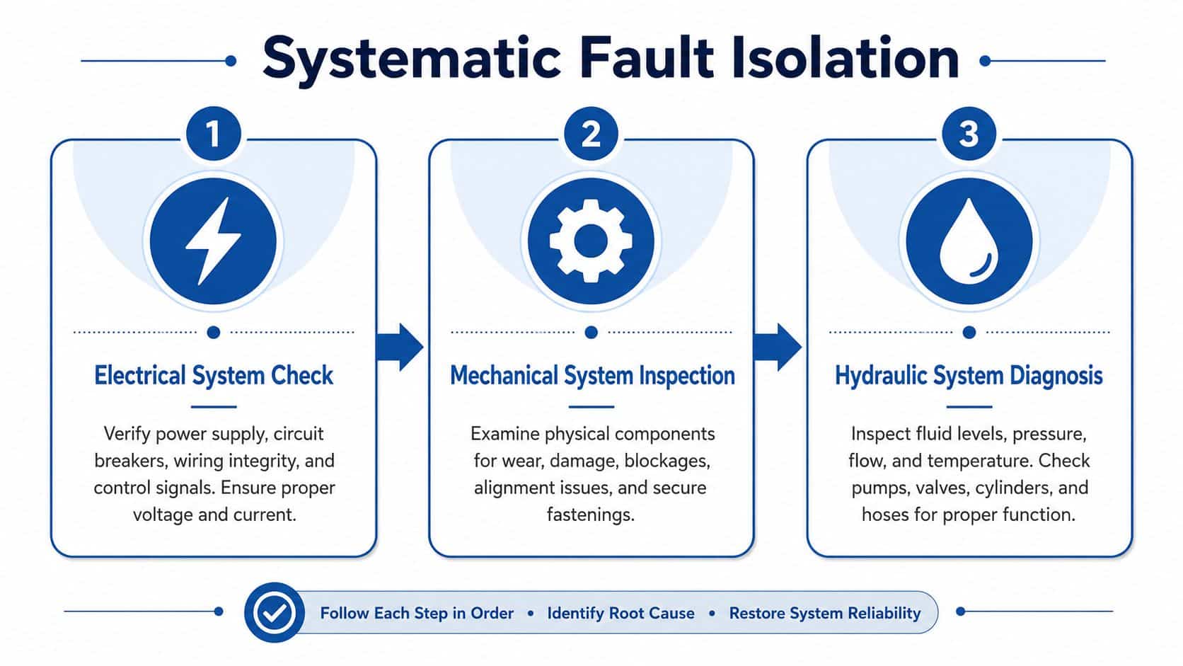
The practical sequence that saves the most time is electrical first, mechanical second, hydraulic third. That order works because the cheapest and fastest eliminations often sit outside the oil path. UK maintenance data shows that 40% of so-called hydraulic failures are, in fact, mechanical or electrical control faults, and the resulting misdiagnosis costs the UK agriculture and materials handling sectors an estimated £87M annually in unnecessary component replacement as outlined in this industry analysis.
Electrical first
If a solenoid valve never receives a proper signal, no amount of pressure testing will fix the symptom. Start by proving supply, control and switching.
Check these points in order:
- Incoming power: Confirm the machine has the correct supply and that protective devices haven't tripped.
- Control voltage: Measure at the coil, not just at the panel.
- Switching logic: Verify limit switches, pressure switches, relays, PLC outputs and emergency stop circuits.
- Connections: Loose terminals, rubbed cables and corroded plugs create intermittent faults that mimic valve or pump problems.
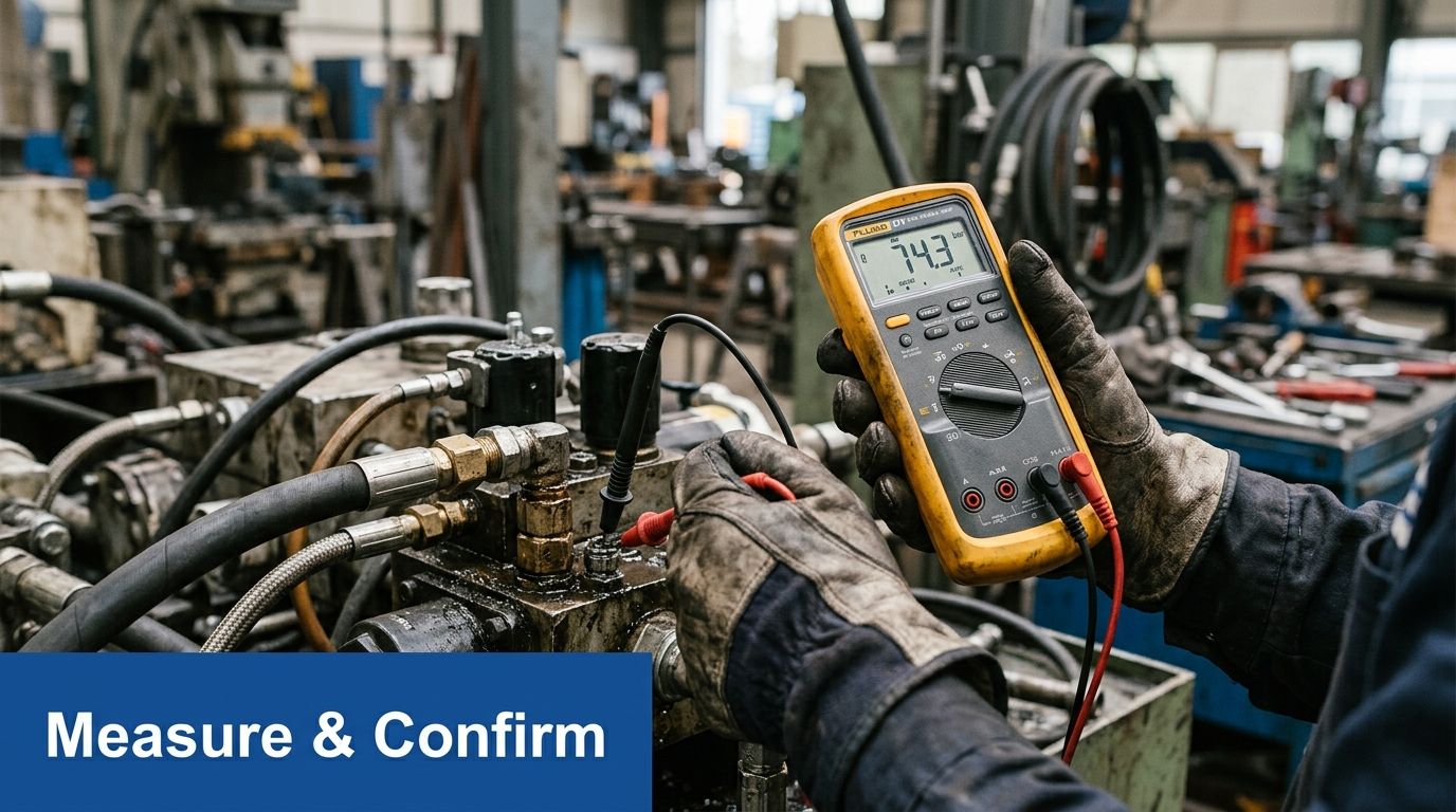
A multimeter and a wiring diagram can eliminate a lot of false hydraulic leads in minutes. On proportional systems, also confirm command signal quality. A weak or unstable control signal can look like a lazy valve when the valve itself is fine.
This walkthrough gives a useful visual reference for structured diagnosis in practice:
Mechanical second
Once electrical control is proved, inspect the machine side before blaming fluid power. A bent linkage, seized pivot, misaligned coupling, jammed guide, over-tight gland or damaged bearing can all produce classic hydraulic symptoms.
I've seen cylinders replaced when the actual fault was a twisted mounting eye loading the rod side. I've seen pumps condemned when the prime mover coupling insert had failed and slipped under load. Neither was a hydraulic problem, even though the complaint sounded hydraulic.
Use simple checks:
- Manual movement where safe: Can the mechanism move freely when isolated?
- Alignment: Check rod, clevis, slides, chain drives and coupled shafts.
- Physical obstruction: Debris, bent guards and damaged stops matter.
- Load path: Has something in the machine started asking for more force than before?
If the mechanism can't move freely, the hydraulic system will only report the struggle. It won't explain it for you.
Hydraulic third
Only after electrical and mechanical causes have been screened should you divide the hydraulic circuit into blocks and isolate it logically.
Treat the system as three broad areas:
| Functional block | What to prove | Typical focus |
|---|---|---|
| Power unit | Is supply energy present and stable | Oil level, suction condition, pump drive, relief setting |
| Control section | Is flow going where it should | CETOP valves, inline valves, flow dividers, priority valves |
| Actuation | Is energy turning into controlled movement | Cylinders, motors, internal leakage, end-load behaviour |
“Divide and conquer” is highly effective. If the power unit develops proper pressure and flow, the fault is downstream. If supply collapses at source, don't chase actuators. If one function is weak while others are normal, compare the affected branch against a healthy one.
On bespoke power packs and complex manifolded systems, work from known reference points. Pressure before and after a valve, temperature across a restriction, and flow behaviour under load tell a clearer story than swapping parts.
The whole-system approach is what makes a troubleshooting methodology practical rather than theoretical. You're not asking “what hydraulic part failed?” You're asking “which domain is creating the symptom?”
Diagnostic Tools and Measurement Techniques
A weak press, a slow ram, or a hot power pack can all look like hydraulic faults. Quite often they are not. This stage is where the theory gets tested with numbers, and where a good engineer separates a hydraulic restriction from a dragging mechanism or an electrical command problem before anyone starts changing parts.
Measure the basics before chasing components
The most useful instruments are still the simple ones, provided they are accurate and used in the right place.
Pressure shows whether the system can develop force. Flow shows whether it can sustain movement. Temperature shows where power is being lost as heat. Electrical readings confirm whether the valve, switch, sensor, or drive is being told to do the job. Those four checks, taken together, stop a mechanical bind or control fault being misread as a hydraulic failure.
A practical fault-finding kit usually includes:
- Calibrated pressure gauges: For pump outlet pressure, work-port pressure, relief valve checks, and pressure drop across filters, coolers, and valves.
- Infrared thermometer or thermal camera: For spotting hot spots around restrictions, bypassing valves, slipping couplings, brakes that are dragging, or bearings running hot.
- Flow meter: For checking pump delivery and separating low-flow faults from low-pressure faults.
- Multimeter: For proving supply voltage, coil resistance, switch continuity, and control signal quality.
- Fluid sampling gear: For checking whether contamination or water ingress has changed the whole fault picture.
For routine service work, a proper hydraulic pressure tester kit earns its keep quickly because it replaces assumptions with repeatable readings.
Use loaded tests carefully
A dead-head test is useful, but only if the machine design allows it and the engineer understands the risk. The actuator is taken to the end of stroke so the system should rise to the relief setting. If pressure still will not build, the loss is usually upstream of the actuator. That points you towards pump wear, a relief valve passing early, a cracked manifold, or internal leakage in the supply path.
Keep the test brief. Watch oil temperature, listen for cavitation, and know the machine limits before starting. Holding a system on relief for longer than needed turns a diagnostic check into a heat-generation exercise.
Thermal checks help here. A relief valve that is bypassing, a restriction across a CETOP valve, or a motor case drain carrying too much leakage will usually create a local heat pattern. A seized bearing, tight pivot, or brake that is failing to release will also show up thermally, which is exactly why this method needs to look beyond the hydraulic circuit first.
Read every number in operating context
Readings taken cold, unloaded, or at the wrong test point can send the job in the wrong direction. Oil viscosity changes with temperature. Internal leakage that is minor at start-up can become serious once the oil is hot. A pump that looks acceptable at idle may fall away badly under working load.
Cross-check the result against the machine specification and the complaint condition. If the fault appears after 30 minutes, test it after 30 minutes. If one function is weak and another is normal, compare both under the same load and temperature. That comparison often saves more time than any single instrument.
High oil temperature matters because it accelerates oxidation, lowers viscosity, and increases internal leakage. Brennan's guidance on steps in troubleshooting hydraulic systems notes that fluid life and component reliability fall away rapidly once operating temperatures are allowed to stay too high.
The same discipline applies outside fluid power. Engineers who also cover plant services will recognise the pattern in this hvac troubleshooting guide. Measure first, compare against design condition, then decide whether the fault is hydraulic, mechanical, or electrical.
Instruments do not diagnose the machine. They give you enough evidence to stop guessing.
Common Failures and Their Root Causes
Field work gets easier when you start with high-probability causes. Across the industry, 80% of hydraulic system failures come from three sources: contaminated fluid, overheating, or internal leaks. That doesn't mean every fault is one of those three. It means they deserve to be checked early, every time.
Hydraulic System Fault Diagnosis Chart
| Symptom | Potential Hydraulic Cause | Potential Mechanical Cause | Potential Electrical Cause |
|---|---|---|---|
| System runs slow | Low effective pump output, contaminated oil affecting valve response, relief valve passing, internal leakage in cylinder or motor | Binding slide, misalignment, seized bearing, overloaded mechanism | Low motor supply, poor control signal to proportional valve, intermittent contact |
| Actuator drifts under load | Internal leakage across piston seal, load-holding valve leakage, spool not seating correctly | Worn pins or linkage movement giving the impression of drift | Solenoid not fully de-energising, control fault holding valve slightly open |
| Excessive heat | Relief valve bypassing, restricted filter, oil too thin at temperature, continuous internal leakage | Excessive friction in pivots, brake drag, mechanical overloading | Motor overcurrent condition, unstable signal causing valve chatter |
| Noisy operation | Cavitation, aeration, suction restriction, low oil level, pressure instability | Coupling wear, loose mountings, resonance through frame | Contactor chatter, poor coil supply, switching instability |
| One function weak, others normal | Sectional valve fault, branch restriction, local cylinder bypass | Bent rod, jammed guide, damaged mechanism on one axis | Failed coil, broken wire, PLC output fault on one function |
| Function works cold then fades hot | Viscosity loss exposing wear, internal leakage increasing with temperature | Expansion tightening a misaligned assembly | Heat-related electrical failure, coil breakdown when warm |
What those patterns usually mean
Contamination is the first place to look because dirty oil doesn't just damage parts. It creates secondary faults. Sticking spools, scored pumps, erratic valves and premature seal wear often come back to fluid condition rather than component design.
That's why regular oil analysis matters. It gives you evidence of wear metals, contamination and fluid condition before the next complaint turns into a strip-down.
Overheating deserves the same attention. Heat is often a symptom, not the original failure. When a machine runs hot, look for where energy is being dumped. Relief flow, restrictions, friction and leakage all leave a thermal signature somewhere.
Internal leaks are the faults that most often fool teams into replacing healthy upstream parts. A pump can be blamed for weak performance when the actual loss is across a cylinder piston or worn valve section further down the circuit.
Don't stop at the first plausible cause
The chart is a starting point, not a verdict. The same symptom can come from different domains, which is exactly why a whole-system troubleshooting methodology works better than a hydraulic-only one.
A slow machine with hot oil might have a bypassing relief valve. It might also have a binding mechanism or a control issue preventing a valve from shifting fully. The symptom doesn't choose the category for you.
Repair Verification and Preventive Documentation
A repair isn't complete when the spanners are put away. It's complete when the machine performs correctly under the conditions that caused the complaint.
Prove the fix under load
Run the equipment through a full operating cycle. If the fault appeared hot, test it hot. If it failed under load, test it under load. Watch the original indicators. Pressure, speed, temperature, noise, control response and load-holding all need to match normal operation.
Rushed jobs reveal their flaws. A machine that “works again” in the workshop may still fail in service because the original trigger condition was never recreated.
Write down what happened
Documentation is one of the few habits that keeps paying back. Record the symptom, the operating conditions, the tests carried out, the readings that mattered, the root cause found and the corrective action taken.
That record shortens the next diagnosis dramatically. UK-based IT and industrial firms report that 85% of recurring hardware faults are resolved significantly faster when historical documentation from the verify and document phase is available to the team as highlighted in this troubleshooting methodology reference.
Good documentation turns one technician's hard-won fix into team knowledge.
There's also a bigger shift behind it. Once teams verify and document consistently, troubleshooting stops being reactive firefighting and starts feeding preventive maintenance, cleaner rebuild standards, better fluid handling and better component selection.
If you need help diagnosing a persistent hydraulic fault, specifying replacement components, or building a more reliable power pack solution, contact MA Hydraulics Ltd. Phone 01724 279508 today, or send us a message.
