
You're usually looking at accumulator sizing because something in the machine isn't behaving as it should. A press bangs harder than expected at changeover. A lift circuit drifts. A clamp loses confidence at the worst point in the cycle. Or procurement has asked for “an accumulator” with almost no operating data, and everyone knows that's how expensive mistakes start.
Hydraulic accumulator sizing isn't just a maths exercise. In practice, it sits at the junction of performance, component life, safety, servicing, and compliance. Get it right and the circuit feels settled and predictable. Get it wrong and the accumulator either does very little, or it becomes another stressed pressure component in a system that already has enough ways to fail.
Why Correct Accumulator Sizing is Crucial
A wrongly sized accumulator usually announces itself through side effects rather than one obvious fault. Hoses twitch. Valves chatter. Cylinders hesitate at the start of travel. Operators describe the machine as harsh, lazy, or inconsistent. The common thread is that the gas volume available inside the accumulator doesn't properly match the job being asked of it.
In a material handling circuit, for example, an undersized unit might not absorb enough of the pressure transient when a directional valve shifts. The result isn't only noise. You can end up loading hoses, seals, manifolds, and valve bodies far more aggressively than the designer intended. On the other hand, a unit that's too large for the available pressure window can feel unresponsive and awkward to tune into the rest of the hydraulic package.
What the accumulator is really doing
Most real applications fall into one or more of these jobs:
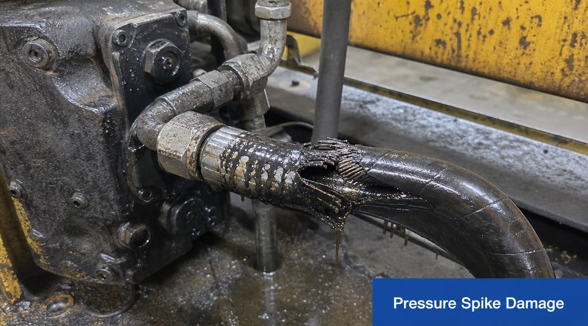
- Shock absorption: Smoothing sudden pressure spikes caused by valve switching, overrunning loads, or abrupt deceleration.
- Energy storage: Holding usable hydraulic energy so the system can meet a short-duration demand without relying entirely on immediate pump flow.
- Pulsation damping: Taking the edge off pump ripple and flow irregularity so downstream components see a steadier pressure profile.
- Leakage compensation: Holding pressure for a period where small internal leakage would otherwise let a cylinder or clamping function relax.
Those are simple descriptions, but each one drives a different sizing approach. A unit selected for pulsation damping won't necessarily suit emergency actuation or a high-volume discharge event.
Practical rule: If you can't state exactly what the accumulator must do in the circuit, you're not ready to size it.
What goes wrong when engineers guess
The costly mistakes tend to be predictable:
| Problem | What it looks like in service | Likely cause |
|---|---|---|
| Pressure drop is too fast | Function won’t complete reliably | Usable volume was overestimated |
| Harsh response remains | Spikes still reach the system | Accumulator volume is too small or positioned badly |
| Sluggish circuit behaviour | Slow reaction after demand | Accumulator is oversized for the pressure band |
| Repeated maintenance issues | Pre-charge complaints and shortened component life | The duty cycle and temperature effects weren’t allowed for |
A correctly sized accumulator supports the circuit. It shouldn't become a workaround for poor pump sizing, bad valve selection, or weak pipework layout. Used properly, it gives the machine a buffer. Used carelessly, it hides a design problem until the repair bill arrives.
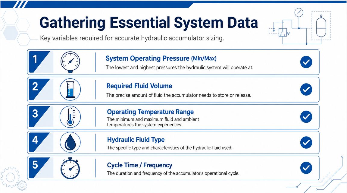
Gathering Your Essential System Data
Before touching a formula, collect the operating facts. Most sizing errors start here, not in the calculation itself. If the pressure range is guessed from a relief setting, or the fluid demand is estimated from memory, the result looks tidy on paper and disappoints on the machine.
Pressures that matter in the real circuit
Start with the minimum working pressure and the maximum working pressure for the function you're supporting. Don't confuse these with the nominal system rating stamped on a component or the relief valve setting on the power pack.
What matters is the pressure window across which the accumulator has to accept and release fluid. If the function must remain effective down to a lower pressure threshold, that lower threshold belongs in your sizing work. If a pressure spike exceeds the normal line pressure during events such as stopping a cylinder under load, you need to understand that too.
A useful data capture sheet should include:
- Minimum operating pressure: The lowest pressure at which the function still has to work properly.
- Maximum operating pressure: The highest pressure the accumulator will reasonably see in service.
- Normal operating band: The pressures seen during routine cycling, not just fault or standby conditions.
Usable fluid volume and cycle demand
The next critical number is the usable fluid volume the accumulator must supply or absorb. This is the quantity of oil moving in or out between your working pressure limits.
That sounds obvious, but it's where many people mix up total accumulator shell volume with deliverable hydraulic volume. They're not the same thing. If a cylinder needs a defined amount of oil to complete a movement, or a clamp must hold pressure while leakage occurs elsewhere, quantify that hydraulic demand first.
If the circuit drawing doesn't give enough confidence, measure the flow and stroke demand on the machine. Field data beats tidy assumptions.
Cycle time matters as well. A slow pressure change allows more thermal exchange with the surroundings. A fast event behaves differently. That affects how closely reality follows the simplest gas law assumption and whether your calculation needs a more conservative view.
Temperature, fluid, and installation details
Temperature shifts change gas behaviour inside the accumulator, and they change how the hydraulic fluid behaves outside it. The relevant issue isn't only workshop temperature. It's the actual range the machine sees, including cold starts, enclosed power unit heat, outdoor operation, and heat soak after repeated cycling.
Collect these details before you specify anything:
- Operating temperature range: Include ambient and fluid conditions the machine sees.
- Hydraulic fluid type: Mineral oil, fire-resistant fluid, or another medium. Seal and bladder compatibility matter.
- Cycle frequency: Frequent cycling increases stress on the gas side and the separator element.
- Mounting and available space: Some accumulator types tolerate orientation and packaging constraints better than others.
- Connection details: Port size and thread standard need to match the circuit without introducing restrictions.
If you're missing one of those items, pause and get it. Hydraulic accumulator sizing punishes incomplete data more quickly than many other hydraulic selection tasks.
The Core Sizing Calculations Explained
Sizing starts with one practical question. How much oil must the accumulator deliver or accept across a defined pressure range without dropping the circuit below its minimum working pressure?

An accumulator is a gas-charged pressure vessel, so the calculation depends on how nitrogen pressure changes as gas volume is compressed and released. On site, poor assumptions often lead to significant expense. A unit can look acceptable on paper, then prove too small during commissioning, or too lightly specified for the duty once temperature swings and cycling are taken into account. In the UK, that risk is not only technical. It also affects safe operation, inspection planning, and pressure system compliance under PSSR 2000.
Start with pre-charge pressure
Set the nitrogen pre-charge pressure, written as P0, before anything else. In general industrial practice, pre-charge is often set at about 80 to 90% of minimum system pressure for many duties, then reviewed against the actual application, temperature range, and maintenance interval.
That setting has direct consequences. If pre-charge is too high, the accumulator may not take in enough oil. If it is too low, the gas is over-compressed in service, separator life suffers, and the usable pressure band is often poorer than expected.
Define the working terms clearly:
- P0 = pre-charge pressure
- P1 = minimum system pressure
- P2 = maximum system pressure
- V0 = nominal accumulator volume
- ΔV = required usable fluid volume
Keep the units consistent throughout the calculation. In UK hydraulic work, that usually means bar and litres.
The engineering principle
The engineering principle is the relationship between gas pressure and volume inside the shell. As oil enters the accumulator, gas volume falls and gas pressure rises. As oil leaves, gas volume increases and pressure drops.
For sizing, the useful oil volume is the change in gas volume between the upper and lower working pressures. That sounds simple, and the maths is manageable, but the result only holds if the pressure points and duty assumptions are right.
A first-pass estimate often uses Boyle's Law under an isothermal assumption. That is a sensible starting point for many designs because it quickly shows whether the required shell size is in the right range.
Isothermal, adiabatic, and polytropic assumptions
The gas law model must match the duty closely enough to avoid an optimistic result.
Isothermal conditions
Use an isothermal assumption where charging and discharging happen slowly enough for heat to move between the gas and its surroundings. This usually suits slower storage, leakage compensation, or pressure maintenance duties.
The advantage is simplicity. The risk is that it can overstate usable volume if the machine cycles faster than expected.
Adiabatic conditions
Use an adiabatic assumption for rapid events where the gas has little time to exchange heat during compression or expansion. Shock damping, pulsation control, and fast emergency movements often sit closer to this case.
In practice, this usually means less usable oil from the same shell size than the isothermal calculation suggests. Engineers who miss that point tend to undersize accumulators for fast-response circuits.
Polytropic behaviour in service
Most working systems live somewhere in between. A polytropic approach reflects that middle ground and is often closer to what happens on an actual machine.
This is the judgement part of sizing. Ask how quickly the event happens, how often it repeats, and how much temperature rise the gas is likely to see over the duty cycle. At MA Hydraulics, we treat that step seriously because it is often the difference between a reliable selection and one that only works in a spreadsheet.
Converting the calculation into a usable specification
Once the theoretical volume is known, check whether it still makes sense as a purchasable, maintainable, and safe assembly. The selected shell size must cover the duty with realistic margin, not only the nominal fluid volume from the equation.
| Selection check | Why it matters |
|---|---|
| Pre-charge choice | Controls how much oil the accumulator can accept and return in service |
| Pressure band | Sets the usable compression range between minimum and maximum working pressure |
| Duty severity | Determines whether an isothermal assumption is acceptable or too optimistic |
| Temperature allowance | Covers cold starts, heat soak, and normal operating variation |
| Standard shell size | Catalogued products rarely match the exact calculated figure, so selection usually rounds up |
One more point matters in UK practice. The shell volume you choose affects more than performance. It also influences installation space, guard design, isolation arrangements, servicing access, and the wider pressure system documentation that should be in place before the machine is handed over.
Worked Examples for Mobile and Industrial Systems
A clamp drifting open halfway through a production cycle, or a loader function slowing when the engine drops to idle, usually points back to the same issue. The accumulator was sized on paper, but not for the duty the machine sees.
The examples below show the practical checks I would expect before signing off a selection. The numbers are illustrative. On a live job, confirm pressures, fluid volume, temperature range, and cycle behaviour on the machine itself. In UK installations, that discipline also supports the pressure system records and safe operating basis expected under PSSR 2000.
Industrial example with leakage compensation
Start with a fixture clamping circuit. The requirement is simple to describe and easy to get wrong. The clamp must hold force for a set dwell time while small internal leakage across valves, seals, or manifolds slowly reduces pressure.
Here, the accumulator is not covering a sharp flow spike. It is supplying a measured oil volume over time across a defined pressure band. Set the minimum acceptable clamp pressure first, then the highest normal system pressure available to charge the unit. After that, establish the oil volume the circuit loses during the hold period. That value is often guessed. It should be measured.
Pre-charge then needs care. Set it too high and the accumulator accepts too little oil. Set it too low and you waste usable pressure range and can shorten bladder life. Once the theoretical shell volume is calculated, select the next practical size up if the duty, temperature swing, or leakage estimate is uncertain.
A usable handover note for this duty should record:
- Function: Maintain clamp pressure during dwell
- Minimum working pressure: Lowest pressure that still holds the part securely
- Maximum system pressure: Normal charging pressure in service
- Oil demand: Measured leakage volume over the full hold time
- Cycle pattern: How often the clamp repeats and how long it remains pressurised
- Temperature range: Cold start and normal running conditions
- Safety items: Isolation, discharge method, pressure indication, and identification for the pressure system file
One mistake shows up repeatedly in factory equipment. The circuit holds pressure on the test bench, then loses it in production because actual dwell time is longer, oil temperature rises, and leakage increases with wear. Size for the actual production condition, not the commissioning snapshot.
Industrial selection judgement
After the calculation, the job becomes practical. Standard shell sizes rarely match the exact figure, so selection usually rounds up. That margin must be deliberate, not excessive.
Too small and the clamp pressure falls away before the end of the cycle. Too large and you add cost, space, stored energy, and maintenance burden without much benefit. For fixed plant in particular, also check whether the installation leaves enough room for guards, charging access, isolation valves, and future replacement. Those details affect serviceability and PSSR compliance just as much as the maths affects performance.
Mobile example with emergency or transient demand
Now take a mobile machine where the accumulator has to support a lift, brake release, or controlled lowering function when pump flow drops away or cannot respond quickly enough. This duty is harsher because pressure does not stay tidy. It moves with load, engine speed, oil temperature, and operator input.
In that case, I would define the event in plain terms first. How much movement is needed, how quickly must it happen, and what is the lowest pressure at which the function is still safe and usable? From there, confirm the highest pressure the machine can supply in normal operation and calculate the oil volume needed for that short event.
Fast events need conservative judgement. If the gas temperature rises during discharge, an isothermal assumption can make the accumulator look better on paper than it will be on the machine. That is one reason mobile applications often end up needing more shell volume than the first pass suggests.
A sound workflow is:
- Define the protected function and the minimum acceptable pressure.
- Confirm the maximum charging pressure available in real service.
- Measure or calculate the oil volume needed for the transient movement.
- Choose a pre-charge suited to the duty and response required.
- Apply margin for temperature, repeat cycling, and real machine variation.
- Select the nearest standard shell size that fits the duty and installation safely.
Packaging pressure causes plenty of bad decisions on mobile equipment. If the available space only suits a smaller shell than the duty requires, the answer is to revise the mounting arrangement, not to force the selection. Undersized accumulators often appear acceptable in mild weather with a lightly loaded machine, then fail to deliver when the oil is cold or the duty becomes repetitive.
Mobile selection judgement
Before ordering a replacement or specifying a new unit, check the physical product against the actual requirement, not only the old part number. MA Hydraulics Ltd supplies compact accumulator sizes such as 0.5 litre, 0.75 litre, and 1 litre units rated at 210 bar with a 1/2" BSP fluid connection. That can suit many mobile circuits, but only after pressure range, pre-charge, gas law assumption, and mounting constraints have been confirmed.
That last point saves money. Replacing like for like is quick, but if the original accumulator was marginal, the same part will give the same trouble.
Selecting the Right Accumulator Type and Safety Factors
A machine can be perfectly sized on paper and still fail in service because the wrong accumulator type was fitted. That usually shows up on site as slow response, short bladder life, unstable pressure control, or a unit that is awkward to charge and unsafe to maintain.

Bladder, diaphragm, and piston compared
Selection starts with duty, not habit. Engineers often have a preferred type, but the right choice depends on response speed, usable volume, installation space, service access, and how forgiving the unit will be in real operating conditions.
| Type | Where it works well | Main strengths | Watch-outs |
|---|---|---|---|
| Bladder | General industrial and mobile hydraulics | Fast response, widely used, good for shock and pulsation duties | Sensitive to incorrect pre-charge and some installation abuses |
| Diaphragm | Compact systems and smaller volume duties | Simple form factor, quick response in small packages | Less flexible when larger volume demand is needed |
| Piston | Higher volume or applications needing a different construction approach | Useful across a broad range of duties and packaging arrangements | Friction, sealing condition, and orientation details deserve attention |
Bladder accumulators are usually the first option for dynamic circuits. They respond quickly and handle pulsation and shock duties well. The trade-off is that they do not tolerate poor charging practice, fluid contamination, or rough installation for long. On mobile plant, I would also check protection from vibration and physical damage before signing off the choice.
Diaphragm units suit smaller volumes and tight spaces. They are often a sensible answer on compact power packs and simpler auxiliary functions where the duty is clear and the required discharge volume is modest. Once the volume demand starts climbing, they become less practical than other options.
Piston accumulators are often chosen where shell size, fluid volume, or construction limits push the application beyond a bladder or diaphragm design. They can solve difficult packaging problems, especially in industrial installations, but they bring their own checks. Seal condition, friction, contamination tolerance, and mounting orientation all matter if you want predictable performance over time.
UK safety and conservative selection
In the UK, an accumulator is not just a sizing exercise. It is a pressure component with stored energy, and that brings legal and practical duties under the Pressure Systems Safety Regulations 2000. The selection has to cover the pressure band, the actual duty cycle, maintenance access, and the safe isolation of the assembly in service.
That changes how sensible engineers apply margin.
A pre-charge set too close to minimum working pressure can leave too little usable oil volume once temperature shifts or gas loss appear in service. A shell chosen with no volume margin may work during commissioning, then disappoint during cold starts, repeated cycling, or heavier production loads. The safer approach is to leave room for operating variation and to confirm that the accumulator, charging equipment, valves, hoses, and protection devices all suit the highest credible pressure condition.
PSSR compliance also has procurement consequences. If the site requires written schemes of examination, certification, or defined maintenance intervals, those requirements should be considered before the type is fixed. It is far easier to choose a unit that can be inspected, isolated, and recharged properly than to force compliance around a poor installation later.
Conservative selection usually costs less than downtime, burst components, or repeat call-outs caused by marginal pressure equipment.
Safety factors that are worth applying
A few checks prevent most expensive mistakes:
- Fluid and seal compatibility: Match the bladder, diaphragm, piston seals, and shell internals to the hydraulic fluid in use.
- Pressure rating across the assembly: Check the accumulator, safety block, shut-off valve, gauge gear, hose or pipework, and fittings as one pressure system.
- Mounting and orientation: Support the unit properly and confirm the chosen type is suitable for the installed position.
- Isolation and discharge: Fit the means to isolate, depressurise, and verify zero energy before maintenance.
- Charging method: Use dry nitrogen, the correct charging kit, and a pre-charge procedure that technicians can repeat reliably.
- Service conditions: Allow for cold starts, heat soak, shock loading, and repeated cycling instead of using catalogue conditions as if they were site conditions.
One final point from experience. Treat replacement work with the same discipline as new design. If an old accumulator failed early, drifted out of pre-charge, or never quite delivered the expected function, that is a warning to review the type and safety margin rather than copy the original part number.
Your Procurement Checklist and Getting Expert Support
A buying mistake usually starts with a rushed replacement. The machine is down, someone sends a photo of the failed accumulator, and procurement asks for "the same again". That approach causes repeat failures, poor gas pre-charge, clearance problems, or a unit that creates fresh compliance work under PSSR 2000 once it lands on site.
Procurement needs a specification that can be quoted, supplied, installed, and maintained safely in the UK.
What to send with an enquiry
Send the technical details that affect duty, pressure equipment selection, and installation:
- Selected shell volume: Give the nominal accumulator size you intend to buy, not only the calculation result from the sizing sheet.
- Pre-charge pressure: State the nitrogen pre-charge target and whether it is to be supplied dry, charged, or charged on site.
- Working pressure band: Include minimum, normal, and maximum operating pressure. A single maximum pressure figure is not enough for correct sizing.
- Usable oil volume required: Make clear whether the accumulator is covering leakage make-up, emergency operation, pulsation damping, or thermal expansion.
- Accumulator type: Confirm bladder, diaphragm, or piston if already chosen, or say where the choice is still open.
- Connection details: List port size, thread form, adaptors, and any hose or manifold limitations.
- Fluid specification: Name the hydraulic fluid and any seal compatibility concerns.
- Temperature and cycle conditions: Include cold starts, ambient range, fast cycling, and any long dwell periods at pressure.
- Space and mounting limits: Provide envelope dimensions, mounting orientation, and access for charging, isolation, inspection, and future replacement.
- Documentation required: State any certification, declaration, test paperwork, or tagging your site standards require.
Photos help, but they do not replace operating data.
What procurement teams often miss
UK buyers often ask for pressure rating and shell size, then leave out the pressure band, the pre-charge, and the actual job the accumulator must do. That is how a part can match the old unit on paper and still be wrong in service.
Replacement work needs the same discipline as a new design. If the previous accumulator lost pre-charge quickly, gave poor response, or failed early, treat that as evidence. Review the duty, mounting, gas setting, and protection hardware before issuing a purchase order.
Good technical support shortens that process. Our team regularly reviews enquiries where the calculation is broadly right but the installation details are not. Isolation method, charging access, certification needs, and service conditions often decide whether the unit is practical to own, not just possible to fit.
If you need a second check before ordering, speak to our team. We can review the operating duty, pressure range, connection details, maintenance access, and UK compliance points so the specification is ready for procurement and safer to install.
