
If you're specifying a mobile hydraulic power unit, you're usually under pressure from two directions at once. The machine has to do real work in a tight space, and procurement wants a clean, defensible specification that won't turn into installation problems, warranty claims, or endless service calls.
That’s where most generic advice falls short. A mobile hydraulic power unit isn't just a pump and tank bolted together. On a trailer, lorry, agricultural machine, service vehicle, or compact plant platform, every choice affects something else. Flow affects cycle time. Pressure affects component life. Reservoir design affects oil condition. Mounting position affects hose routing, access, and vibration.
Get the specification right and the unit disappears into the machine. It starts, lifts, tips, drives, holds, and returns without fuss. Get it wrong and you end up compensating for a bad design with bigger motors, hotter oil, noisy pumps, restrictive fittings, and maintenance headaches.
What Is a Mobile Hydraulic Power Unit
A mobile hydraulic power unit is a self-contained hydraulic power source built to travel with the machine rather than sit in a fixed plant room. It converts mechanical or electrical input into hydraulic flow and pressure, then sends that energy to cylinders, motors, or other hydraulic functions on the vehicle or mobile plant.
In practical terms, it solves a familiar engineering problem. You need a trailer body to tip, a stabiliser leg to extend, a winch to pull, a small crane to slew, or a service body to operate auxiliary functions. You need high force from a compact package, mounted on the chassis, with reliable control and straightforward servicing.

What it does on a machine
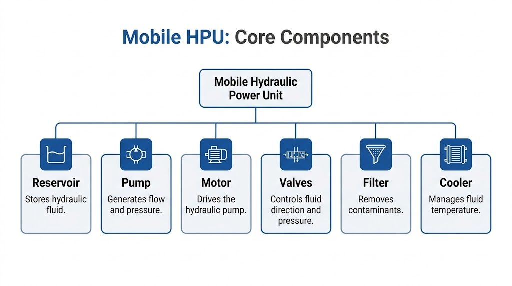
A mobile HPU usually combines the same core building blocks in one assembly:
- Power source such as a DC motor, AC motor, engine drive, or PTO-driven input
- Pump to generate hydraulic flow
- Reservoir to store and condition the oil
- Valve arrangement to direct, limit, and hold pressure
- Filtration and ancillary parts to protect the circuit
That compact layout is why mobile units are used across UK construction plant, agriculture, transport equipment, recovery vehicles, and materials handling. The principle is simple. The specification is not.
For a clear primer on the underlying principle of fluid power, MA Hydraulics has a useful explainer on how hydraulics work.
Why the UK heritage matters
Hydraulics in Britain didn't begin with modern compact power packs. The roots go much deeper. Joseph Bramah, an English engineer from Yorkshire, patented the hydraulic press in 1795, applying Pascal’s principle and laying the groundwork for force multiplication in hydraulic systems. That UK-born development helped shape the compact high-force systems used now, with modern hydraulic systems reaching pressures exceeding 5,000 psi (over 340 bar) according to this history of hydraulic power.
Practical rule: A mobile hydraulic power unit isn't specified by asking, “What unit have you got on the shelf?” It’s specified by asking, “What work must the machine do, how fast, how often, and from what available power source?”
That’s the right starting point. Not the catalogue photo.
The Core Components Inside Your HPU
A mobile HPU works properly when the parts are matched, not merely assembled. Engineers who struggle with hydraulic units usually aren't dealing with one bad component. They’re dealing with a mismatch between pump, motor, valve settings, oil volume, and line sizing.
Think of the unit as a compact circulatory system. The reservoir stores the fluid, the pump moves it, the motor or prime mover drives the pump, the valves tell it where to go, the filter keeps it clean, and the cooler controls temperature when duty demands it.
Pump and drive arrangement
The pump is the component that creates flow. Pressure only builds when the circuit resists that flow. That distinction matters because specifiers often ask for “more pressure” when the actual issue is inadequate flow, poor valve selection, or excessive restriction in the lines.
On mobile equipment, gear pumps are common because they’re compact, sturdy, and cost-effective. They suit many tipping, lifting, clamping, and auxiliary circuits well. In more demanding systems, the drive and control arrangement may point towards a different pump strategy, especially where fine control, multiple simultaneous functions, or changing load conditions matter.
The pump has to be driven by something. That may be:
- A DC electric motor on battery-powered or vehicle electrical applications
- An AC motor on mobile equipment that operates from external site power
- A PTO and gearbox arrangement where the vehicle driveline supplies mechanical input
- A small engine drive for stand-alone mobile plant or remote service equipment
The wrong habit is choosing the drive first and forcing the hydraulics to fit. The better method is to define the hydraulic job, then confirm whether the available prime mover can supply it repeatedly without overheating, overloading, or dropping performance.
Reservoir and oil management
The reservoir isn't just a storage box. It gives oil time to de-aerate, helps contaminants settle out before filtration catches them, and provides a thermal buffer. On mobile machinery, packaging pressure often pushes reservoir size down too far. That usually comes back as high oil temperature, frothing, poor suction conditions, and short component life.
Material choice also matters. A mobile machine may need low weight, corrosion resistance, or better heat dissipation depending on duty and environment. Shape matters too. A tank that fits the available envelope but leaves no service access isn't a smart design.
Watch the basics:
- Suction arrangement: Keep it short, adequately sized, and protected from air ingress.
- Return entry: Avoid arrangements that churn the oil directly above the suction zone.
- Breathing: A poor breather strategy lets contamination enter every time the oil level changes.
- Access: If no one can inspect, drain, or clean the reservoir properly, maintenance gets skipped.
A reservoir that only satisfies the CAD model often causes the field problem six months later.
Valves, manifolds and control logic
The valves control direction, pressure, sequence, and holding. They’re where a mobile HPU either feels predictable or frustrating. A simple trailer tipper might only need a straightforward directional and relief arrangement. A service vehicle with several functions may need load holding, priority flow, counterbalance protection, and electrically switched sections.
This is also where a manifold can clean up a design. Instead of multiple inline valves, tees, adaptors, and hose runs, a manifold can integrate the logic into one compact block. That reduces leak paths, shortens the hydraulic route, and makes troubleshooting easier.
Common valve functions include:
- Directional control for extend, retract, lift, lower, or motor reversal
- Pressure relief to protect the system from overload
- Check and load-holding functions where the load must stay put
- Flow control where actuator speed needs managing
- Proportional control where smooth variable movement matters
Filtration and cooling
The filter protects the whole system from what kills most hydraulic assemblies in service, dirt, wear debris, and contamination introduced during maintenance. A good unit design makes filter changes realistic. A bad one puts the element behind guards, brackets, and hoses, then wonders why servicing slips.
The cooler is not mandatory on every mobile HPU, but ignoring heat is expensive. Intermittent circuits may cope with tank cooling alone. Continuous or repeated-duty applications often need more deliberate thermal control.
A sound component stack usually includes these checks before release:
| Component area | What to confirm |
|---|---|
| Pump | Displacement, rotation, pressure capability, mounting |
| Motor or drive | Voltage or input type, duty, starting load, space claim |
| Reservoir | Usable oil volume, filler and breather access, return layout |
| Valves | Function logic, relief setting, holding requirement, actuation type |
| Filter | Location, element access, contamination control strategy |
| Cooler | Whether duty cycle and ambient conditions justify one |
If those six areas align, the mobile HPU usually behaves well in service. If they don't, no amount of downstream adjustment will make it a tidy machine.
Why Choose a Mobile Hydraulic Power Unit
The reason engineers keep coming back to the mobile hydraulic power unit is simple. It delivers serious force from a compact package, and it does that in places where mechanical linkages, shafts, and cable systems become awkward, bulky, or difficult to control.
That compact force density is the primary advantage. A mobile machine rarely has generous installation space. You’ve got chassis rails, guards, payload limits, bodywork, electrical systems, and access constraints all competing for room. Hydraulics let you generate power in one position and apply it somewhere else through hose runs and control valves rather than through rigid driveline geometry.
Why hydraulics won over older mobile systems
The historical shift matters because it shows why the design logic still holds. The 1960s marked the UK's shift to fully hydraulic mobile machinery, replacing cable-and-winch systems. During that move, average operating pressures rose from around 1,500 psi to over 3,000 psi, and firms such as JCB used advanced pump designs that increased loader productivity by 40 to 50% while some agricultural tasks saw manpower needs reduced by 60 to 80%, as outlined in this review of construction equipment hydraulics.
That change wasn't just about more power. It was about control. Mechanical systems can do a lot, but once you need smooth actuation, compact installation, repeatable load handling, and multiple independent functions, hydraulics become the more practical route.
The practical advantages on modern UK plant
A mobile HPU makes sense when the application needs some mix of the following:
- Compact packaging: Useful where the machine envelope is tight.
- Flexible installation: Hoses can route power around articulation points, bodywork, and guarded areas.
- High working force: Hydraulic cylinders and motors handle demanding loads without heavy mechanical transmissions.
- Dirty-environment resilience: Construction, agriculture, and recovery work all expose equipment to mud, vibration, and impact.
- Modular control options: Manual, solenoid, and proportional systems can all be built around the same basic hydraulic principle.
For agricultural applications in particular, equipment layouts often depend heavily on hydraulic integration, and broader machinery planning resources such as farm machinery with hydraulics can be useful when you're looking at the machine as a complete working asset rather than just the power pack.
Hydraulics aren't chosen because they're fashionable. They're chosen because they let one machine do heavy work in a compact footprint with manageable control complexity.
The trade-off is that they reward good specification and punish lazy specification. That’s why sizing matters.
Sizing and Performance Calculations for Specifiers
Most mobile HPU problems begin before the unit is built. The spec was based on a guessed pressure, a rough flow figure, or a copied bill of materials from a different machine. That approach nearly always creates one of two bad outcomes. The unit is underpowered and slow, or it's oversized and wasteful.
Start with the job. What has to move, how far, how fast, and under what load? Only then do you convert that requirement into pressure, flow, and power.
The hydraulic triangle
The core relationship for specifiers is:
Power (kW) = (Pressure (bar) x Flow (L/min)) / 600
That formula is useful because it ties the whole design together. If the required pressure climbs, the available flow from a given motor power drops. If you want faster movement, the flow requirement rises. If you want both high pressure and high flow, the prime mover and heat management need to support it.
Three inputs drive most early calculations:
- Force or torque required
- Speed of movement
- Duty cycle
Work backwards from the actuator
If the application uses a cylinder, start there. The cylinder bore and effective area determine how much pressure is needed to create the force. The stroke and target movement time determine the flow requirement.
If the application uses a hydraulic motor, the target torque and speed set the requirement instead.
A simple thought process works well:
- Load first: What force must the ram generate, or what torque must the motor deliver?
- Speed second: How quickly must the function complete in real use?
- Losses third: What pressure drop will occur through valves, hoses, fittings, and any load-holding devices?
- Duty fourth: Is this a short intermittent function or something that repeats frequently?
A practical example for a trailer tipper
Take a small tipper application. The instinct is often to ask for the fastest cycle possible. That usually creates unnecessary motor size, higher current draw on DC systems, and more heat than the duty justifies.
A better method is to define the acceptable tip time, the likely loaded condition, and the cylinder arrangement. Then check:
- whether the cylinder can produce the required lifting force at a realistic working pressure
- whether the pump displacement can supply enough flow for the target tip speed
- whether the available electrical or mechanical drive can sustain the hydraulic power required
- whether return and lowering behaviour are controlled, not just extension speed
Herein lies the flaw of copied specifications: A unit that works on one trailer may be poor on another because body geometry, pivot position, cylinder mounting angle, and payload distribution all change the pressure demand throughout the stroke.
For a deeper design route, MA Hydraulics also provides guidance on hydraulic power pack design.
Requirement gathering before calculation
Use a short capture sheet before anyone sizes the pump or motor.
| Parameter | Required Value | Unit |
|---|---|---|
| Application type | ||
| Actuator type | ||
| Required force or torque | ||
| Stroke or rotational speed | ||
| Target cycle time | ||
| Maximum working pressure | ||
| Required flow | ||
| Duty cycle | ||
| Available power source | ||
| Installation space envelope | ||
| Ambient operating conditions | ||
| Control method |
That checklist prevents the usual errors, especially “needs to be powerful” and “same as the last one” passing as engineering inputs.
Pressure isn’t a design target on its own
A lot of specifications treat pressure as the main number. It isn’t. Pressure is a result of resistance to flow. You don't select a high-pressure unit because high pressure sounds capable. You select components that safely cover the force requirement with margin for normal operating losses.
That distinction matters in procurement. Two units with the same maximum pressure rating can behave very differently because one has the right flow for the cycle and the other doesn’t.
If the machine feels slow, don't assume it needs more pressure. In many cases it needs more usable flow, less restriction, or a different control arrangement.
Duty cycle changes everything
A mobile hydraulic power unit used for brief intermittent tipping has very different thermal demands from one powering repeated auxiliary functions through the day. The parts may look similar on paper, but service life and oil condition won’t be similar if the duty assumptions are wrong.
Check these points carefully:
- Intermittent operation: Often allows a compact tank and simpler thermal strategy.
- Frequent cycling: Increases heat load and raises the importance of reservoir design and filtration.
- Continuous or near-continuous use: May require cooling, more capable motor sizing, and a different valve strategy.
- Cold-start use outdoors: Affects viscosity, suction behaviour, and start-up loading.
Sizing a mobile HPU properly isn’t about chasing the biggest numbers. It’s about matching the system to the job with enough headroom for real operating conditions, not imagined brochure conditions.
Mounting Integration and Control Options
A mobile HPU that looks right on a datasheet can still be troublesome on the machine. I have seen units with the correct pressure and flow become expensive service problems because the tank could not be filled cleanly, the filter could not be changed in situ, or the hose runs were forced around sharp structure members. Integration decides whether the unit works well in service or causes repeat failures.
The mounting position needs to be chosen around the machine, not around empty space in a CAD model. Low and central often helps with stability and keeps hose lengths sensible, but it can also put the assembly in the firing line for spray, salt, thrown debris, and kerb strikes. Higher mounting can improve protection, yet it may complicate priming, increase noise exposure, or make routine checks awkward. On UK road-going and off-highway equipment, those trade-offs matter because weather, contamination, and access constraints are part of normal use.

Mounting on the chassis
A sound mounting arrangement has to carry the wet weight of the unit, withstand vibration and shock, and leave enough clearance to service the parts that will need attention. That usually means checking more than bolt size. Bracket stiffness, weld quality, local chassis reinforcement, and the effect of dynamic loading all need attention, particularly on mobile plant that sees rough ground or repeated stop-start duty.
Good installations usually provide:
- Support for the full operating mass including oil, guards, and dynamic loading in service
- Protection from impact and contamination using sensible positioning and, where needed, shields or guarding
- Service access to filters, breathers, filler points, level gauges, terminals, and valve adjustments
- Controlled hose and cable routing with proper bend radius, clamping, abrasion protection, and strain relief
A common mistake is approving a layout that can be assembled once in production but cannot be maintained in the field. If an engineer has to remove covers, pipework, or adjacent structure just to change a return filter element, the design will cost more over the machine life than it saved on the drawing.
Movement is another frequent problem. If the mounting frame flexes, fittings loosen, rigid pipework cracks, and electrical connections suffer. We generally prefer a mounting arrangement that is stiff enough to control motion but still realistic about the chassis behaviour it is attached to. On mobile equipment, trying to make one part perfectly rigid while the surrounding structure moves can create stress concentration elsewhere.
PTO and power input choices
The drive arrangement needs to suit how the machine works.
On mechanically driven units, the PTO, coupling, pump mounting, and expected operating speed all need to line up properly. A poor PTO installation rarely fails for one dramatic reason. It usually shows up first as noise, heat, coupling wear, seal problems, or poor pump life. Available engine speed range matters as well. If the pump only performs properly at an engine speed the operator seldom uses, the system will disappoint in normal service.
Electrically driven units bring a different set of checks. Battery voltage drop, cable sizing, earthing quality, contactor selection, and restart conditions all affect reliability. A DC motor that starts happily on a bench can struggle on the vehicle after a cold night, particularly if it has to restart against residual pressure. For many mobile applications, the right answer is not merely "electric" or "PTO". It is the option that fits the duty cycle, available power source, and packaging constraints with the fewest compromises.
| Input type | Typical strength | Typical trade-off |
|---|---|---|
| DC electric | Compact, self-contained, straightforward to package | Limited by battery condition, cable losses, and duty cycle |
| AC electric | Useful where mains or generator supply is available | Ties the unit to an external power source |
| PTO drive | Suits vehicle-based equipment with regular engine availability | Needs careful mechanical integration and speed matching |
| Engine drive | Independent of host machine power systems | Adds noise, fuel use, exhaust considerations, and service work |
Control options from simple to precise
Control specification should start with operator use, fault finding, and safety logic. A single tipping function may be best served by a manual valve with clear detents and predictable behaviour. A machine with multiple auxiliary services, remote functions, or interlocks will usually justify solenoid control. Where the operator needs fine speed control or smooth movement under varying load, proportional control can be worth the extra cost and setup effort.
Typical arrangements include:
- Manual lever valves for simple local operation and straightforward field service
- Solenoid-operated valves for switch control, interlocks, and easier integration with machine electrics
- Proportional valves where movement quality, repeatability, or variable speed control matter
- Integrated manifolds to combine functions in less space and reduce external hose connections
There is a trade-off here. Simpler valve arrangements are usually easier to diagnose on site and cheaper to replace. More integrated systems can reduce leak paths, improve packaging, and tidy up the installation, but they need clearer documentation and more discipline in commissioning.
That is often where bespoke manifold design earns its place. On a crowded mobile chassis, reducing external pipework and grouping valve functions into a compact assembly can improve reliability and make the unit easier to protect. At MA Hydraulics, we use that approach where space is limited, control logic is more involved, or the customer needs a unit built around realities of the host machine rather than a generic catalogue layout.
The best installations are the ones that still make sense five years later, in winter, with mud on the chassis and a technician trying to service them outdoors.
Safety and Maintenance Best Practices
Hydraulic systems deserve respect because they store and transmit serious energy in a small space. On mobile equipment, that risk is amplified by weather, dirt, vibration, rushed repairs, and the fact that many faults appear first in the field rather than in a clean workshop.
The biggest mistake is treating hydraulic maintenance as visual housekeeping. It isn't. A hose that looks acceptable can still be damaged internally. A fitting that only seeps under peak load can still create a hazardous failure. A circuit that seems sluggish can be signalling contamination, aeration, or relief problems long before a major breakdown.
Safety practices that aren't optional
Before anyone touches the system, the circuit needs to be made safe. That means isolating power where possible, lowering or mechanically supporting suspended loads, and de-pressurising the hydraulic side properly. Never assume pressure has bled away just because the machine is switched off.
High-pressure fluid injection injuries are one of the most serious hazards in this work. A tiny leak can penetrate skin. That’s why leak detection with hands is unacceptable. Use the right inspection method, wear the right PPE, and treat every suspected high-pressure leak as dangerous.
A sound field routine usually includes:
- Depressurise first: Confirm stored hydraulic energy has been safely released.
- Secure the load: Don’t rely on hydraulic holding alone during maintenance.
- Inspect hoses and fittings visually: Look for abrasion, crushing, weeping, movement, and damaged protection.
- Check mounting hardware: A loose power unit often causes secondary hydraulic failures.
- Verify cleanliness during service: Open ports and dirty funnels undo good maintenance quickly.
Preventive maintenance beats reactive repair
Reactive repair costs more than it first appears because the component that failed is rarely the whole problem. A failed pump may have been damaged by dirty oil. A damaged valve may have been fed debris from a deteriorating hose. Replacing the obvious failed part without correcting the root cause usually repeats the failure.
That’s why preventive maintenance matters. For UK operators, the lack of clear maintenance interval data often pushes teams into reactive repair, but investing in preventive maintenance, including regular fluid analysis and filter changes based on operating hours and conditions, can reduce the risk of catastrophic pump or valve failure and significantly extend service life, as noted in this discussion of mobile hydraulic system maintenance.
A hydraulic unit usually gives warning before it fails. The trouble is that people often hear the warning and keep working.
What to monitor in normal service
You don't need an elaborate condition-monitoring programme to catch many HPU issues early. You do need consistency.
Pay attention to:
- Oil condition: Darkening, cloudiness, foaming, or burnt smell all justify investigation.
- Filter servicing: A blocked or neglected element increases bypass risk and downstream wear.
- Temperature behaviour: A hotter-than-usual unit tells you something has changed.
- Noise changes: Cavitation, aeration, bearing wear, and relief chatter all have distinct sound patterns.
- Cycle quality: Jerky movement, drift, or slowing under normal load points to a developing fault.
A maintenance schedule for a mobile hydraulic power unit should reflect how the machine is used, not how it was expected to be used when first purchased. Outdoor storage, dirty sites, repeated short cycles, and infrequent but severe peak loading all change what “normal” maintenance ought to be.
Your Bespoke HPU Build and Ordering Checklist
A mobile hydraulic power unit should be treated as a machine sub-system, not a generic commodity. The right build depends on the job, the available power source, the installation space, the control expectation, and the maintenance reality after handover.
That’s why the most productive technical conversations happen when the specifier arrives with operational detail rather than a guessed pump size. If the application is being financed or acquired as part of a broader plant strategy, commercial planning resources such as heavy equipment leasing for construction companies can also help frame how the equipment will be deployed and supported over its working life.
What to gather before you enquire
Bring these details together before requesting a quotation or design review:
-
Application description
State what the unit has to do. Tipping body, recovery winch, stabiliser leg, clamp, auger drive, steering assist, or multi-function service body all point in different directions. -
Actuator details
Include cylinder bore and stroke, or motor torque and speed needs if known. -
Load requirement
Explain the actual working load, not the ideal one. Include awkward conditions such as incline starts, off-centre loads, or sticky mechanisms. -
Required speed
Give the acceptable cycle time for lift, lower, extend, retract, or motor speed. -
Duty cycle
Say whether the function is occasional, repeated, or close to continuous. -
Available power source
Note voltage, PTO availability, engine drive option, or any supply limitations. -
Space envelope
Provide dimensions, mounting orientation constraints, and access restrictions. -
Control method
Manual, pendant, cab switch, remote, interlocked solenoid, or proportional. -
Environmental conditions
Include outdoor exposure, washdown, dirt, temperature variation, and corrosion risk. -
Service priorities
Mention if rapid filter access, hard guarding, noise reduction, or parts commonality matters.
What a good enquiry achieves
A good enquiry shortens the design cycle and reduces revision work. It also prevents the common trap where procurement compares two units on purchase price alone even though they differ in control logic, build detail, filtration approach, and expected service life.
If you're looking for a customized solution rather than an off-the-shelf compromise, MA Hydraulics provides bespoke powerpacks for mobile and industrial applications based on application requirements and component matching.
The strongest specifications are usually the simplest to operate. They do the required work, fit the available space, and stay maintainable after the machine leaves the workshop.
If you need help specifying a mobile hydraulic power unit, speak to MA Hydraulics Ltd. We can help you turn application data into a practical build specification for mobile plant, transport equipment, agricultural machinery, and bespoke hydraulic systems. Phone 01724 279508 today, or send us a message.
