A machine stalls on site. The operator says the boom was slow all morning, then stopped under load. In the workshop, someone points at the cylinder. Someone else blames the pump. The maintenance manager wants the fastest route back into service, but also wants to know why it failed in the first place.
That’s usually where the core question appears. Not “which part is broken?” but how do hydraulics work well enough that the right fault can be found, the right component can be specified, and the same issue doesn’t come back in six weeks.
Hydraulics aren’t mysterious. They’re disciplined. A hydraulic system takes mechanical input, converts it into fluid power, controls that power through valves and manifolds, and turns it back into usable force or motion at the actuator. When the design is right, the system is compact, controllable, and extremely capable. When the design is wrong, or maintenance slips, the same system becomes hot, noisy, inefficient, and unreliable.
For UK engineers, fitters, OEMs, and MRO teams, the details matter. Pressure ranges matter. Filtration matters. So do component choices such as gear pumps, CETOP valves, flow dividers, and compact power packs. In practice, the difference between a dependable machine and a troublesome one usually comes down to getting the fundamentals right.
Introduction The Unseen Force Powering Modern Industry
Walk around any yard, farm, steelworks, or manufacturing plant and you’ll see hydraulics doing the heavy work without drawing much attention to themselves.
An excavator lifts and crowds with smooth control. A forklift raises a load that would be impossible by direct mechanical effort alone. A press forms steel with the sort of force that would be impractical to generate through simple linkages. The operator pulls a lever, presses a switch, or moves a joystick. The machine responds immediately.
That response comes from hydraulic power.
Why hydraulics still dominate hard-working machinery
Hydraulics remain the preferred answer wherever a machine needs high force, compact packaging, and controlled movement. That’s why they’re common in mobile plant, agricultural machinery, lifting equipment, presses, recycling systems, and industrial automation.
The reason is simple. Hydraulic systems let engineers transmit significant force through relatively compact components. You can place the power source where it suits the machine layout, route fluid through hoses, pipes, or manifolds, and apply that power exactly where the work has to happen.
What engineers need to understand in practice
A basic school-level explanation isn’t enough when you’re selecting a pump, tracing pressure loss, dealing with heat, or trying to understand why a machine drifts under load.
The practical questions are usually these:
- Where is pressure created: At the resistance point, not “stored” in the pump in the way many non-specialists assume.
- What does the pump really do: It creates flow. Pressure appears when that flow meets resistance.
- Why do systems fail early: Often because of contamination, poor filtration, wrong component matching, or bad circuit layout.
- What keeps a system safe and compliant: Correct design, disciplined maintenance, and proper examination under UK requirements.
Hydraulics reward good engineering. They also expose shortcuts very quickly.
The Core Principle Force Multiplication with Pascal's Law
A maintenance team sees this principle every time a compact power pack lifts a heavy platform or a small hydraulic cylinder clamps a large fabrication firmly in place. The input force is modest. The output force is not. That result comes from pressure acting on area.
Pascal’s Law states that pressure applied to a confined fluid is transmitted equally in all directions. In hydraulic engineering, that is the starting point for force generation, whether the system uses a simple hand pump, a Vivoil gear pump, or a Hydronit DC power pack on a tail lift or access platform.
Pascal set out the principle in the seventeenth century, and Bramah turned it into a working press in London not long after. The idea is old. The engineering use of it is still current across UK manufacturing, plant, lifting, waste handling, and mobile equipment. Hydraulics also support a sizeable UK industrial sector worth £2.8 billion annually to UK GDP (BFPA industry overview). Well-designed hydraulic transmissions can also operate at up to 85% efficiency in the right duty cycle and layout (Energy Education on hydraulic systems efficiency).
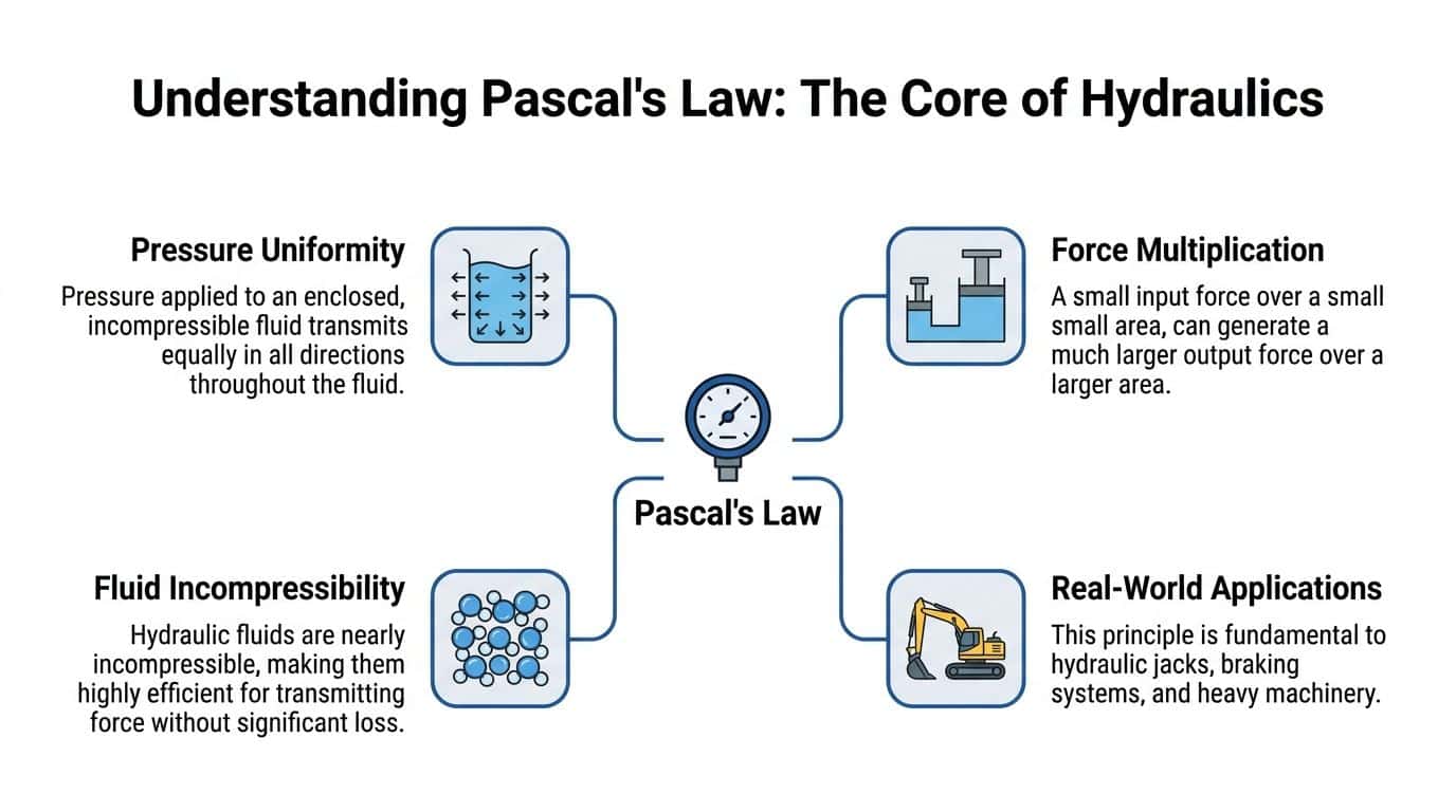
Pressure is the same. Force changes with area
The working relationship is straightforward:
F1 / A1 = F2 / A2
Where:
- F is force
- A is piston area
If pressure in the fluid is equal, a larger piston produces more force because the pressure acts across more area. That is why a relatively small actuator can control or support much heavier loads than the input effort might suggest at first glance.
On real equipment, that does not mean the system gets something for nothing. Higher output force usually means lower actuator speed unless the pump can supply more flow. That trade-off matters in every specification. A press may prioritise force and accept a slow approach speed. A tipping trailer or scissor lift may need a balance between lifting force, cycle time, motor size, oil volume, and battery capacity.
A practical piston example
Use a simple metric example.
An input piston with an area of 10 cm² at 10 bar produces 1,000 N of force. Apply that same pressure to an output piston with an area of 1,000 cm², and the output force becomes 100,000 N. The force ratio follows the area ratio.
That is the part many buyers and junior engineers miss. The larger piston needs far more oil to move the same distance. If the pump flow is limited, the actuator will be strong but slow. In practice, that is why component matching matters. Pair the wrong cylinder size with a small power pack and the machine will meet force on paper but miss the required cycle time in service.
Practical rule: Hydraulics multiply force by using pressure over area. The price is paid in flow, speed, and heat.
Why incompressible fluid matters
Hydraulic oil is used because it is nearly incompressible under normal operating conditions. That gives the system stiffness and predictable response. Directional control stays sharper, load holding is better, and the actuator motion is easier to manage.
Air in the oil changes that immediately. A circuit with entrained air feels soft, moves unevenly, and often gets noisy. On a UK site, that usually shows up as jerky cylinder motion, poor platform stability, or a press that will not repeat accurately. It also creates a safety concern if the application falls within PSSR duties, because inconsistent pressure behaviour is not something to ignore on pressurised equipment.
The engineering takeaway
Hydraulics work because confined fluid transmits pressure uniformly, and engineers use that pressure across different areas to get the force the job demands. The principle is simple. Applying it properly is not.
Good hydraulic design means choosing the right pressure level, cylinder bore, pump displacement, valve arrangement, and fluid volume for the duty. Get those choices right and a compact system delivers controlled, repeatable force in a package that suits real industrial use in the UK.
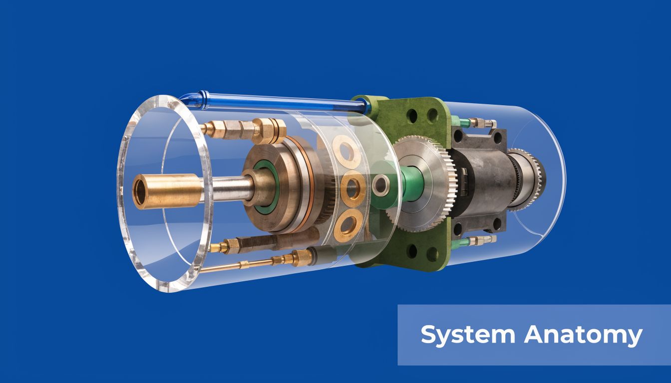
Anatomy of a Hydraulic System Key Components Explained
A hydraulic system only performs well when each component does its job properly. The easiest way to think about it is as a working assembly rather than a pile of parts. The reservoir stores and conditions the oil. The pump creates flow. Valves control it. Actuators turn it into motion. Filtration and supporting hardware keep the whole arrangement alive.
Reservoir and fluid conditioning
The reservoir does more than hold oil.
It gives the fluid space to settle, release air, and shed heat before the next cycle. In a well-designed system, the tank size, return arrangement, and suction layout all help the pump receive a stable oil supply. If the reservoir is poorly arranged, the system often suffers from aeration, overheating, or recurring contamination issues.
Pay attention to these points:
- Suction conditions: The pump needs a clean, unrestricted feed. Starved suction shortens pump life quickly.
- Return placement: Returning oil badly can churn the tank and reintroduce air.
- Breathing and cleanliness: If dirt gets into the tank, it won’t stay in the tank. It goes through the whole circuit.
Pump types and what they really do
The pump is often called the heart of the system, which is a useful comparison if it doesn’t become misleading.
A hydraulic pump does not create pressure directly. It creates flow. Pressure appears when the system resists that flow. That distinction matters when diagnosing faults.
In many mobile and compact industrial systems, gear pumps are a practical choice because they’re dependable, economical, and straightforward to package. Engineers regularly use unidirectional and reversible gear pumps where reliability and serviceability matter more than ultra-fine control. Vivoil gear pumps are a familiar example in this category.
Where compact integrated power is needed, mini power units built around motor, tank, pump, and valve functions can be the cleaner solution. Hydronit packs are commonly used where space is tight and installation needs to stay simple.
Valves are where control happens
Valves decide what the system does.
A basic directional valve determines where flow goes. Pressure control valves protect the system and manage force. Flow controls shape actuator speed. In more demanding circuits, proportional valves allow finer motion control than a simple on/off directional valve.
Common valve groupings include:
- CETOP directional valves: Good for modular industrial assemblies and easier servicing.
- Inline cartridge or circuit valves: Useful where compactness and manifold integration matter.
- Proportional valves: Chosen where smoother or more variable control is required.
What doesn’t work is choosing valves only by port size. The correct selection depends on flow, pressure, response, duty cycle, and how the machine operates.
A valve that fits the manifold but doesn’t suit the duty is still the wrong valve.
Actuators convert fluid power into work
Actuators are the business end of the system.
A cylinder creates linear movement. That makes it the obvious choice for lifting, clamping, pressing, tipping, and pushing. A hydraulic motor creates rotary motion, which suits conveyors, augers, winches, drives, and powered attachments.
Selection comes down to the job:
| Hydraulic Pump Type Comparison | Pressure Range (bar) | Efficiency | Cost | Common UK Application |
|---|---|---|---|---|
| Gear pump | Low to medium | Good practical efficiency | Lower | Agriculture, mobile plant, compact power packs |
| Reversible gear pump | Low to medium | Good practical efficiency | Lower to medium | Mobile machinery with bidirectional requirements |
| Power pack integrated pump set | Application dependent | Depends on overall circuit design | Medium | Lifts, compact industrial systems, auxiliary functions |
The table is intentionally qualitative where exact figures aren’t available for each pump type. In practice, engineers should match displacement, speed, and duty to the machine rather than buying on category alone.
Filtration, manifolds, couplings and the overlooked support parts
Most poor systems don’t fail because the headline component looked wrong on paper. They fail because support details were treated as secondary.
The commonly overlooked items are often the most important:
- Filters: OMT and similar filtration hardware are there to protect every moving surface downstream.
- Manifolds: A clean manifold design reduces leak paths, shortens plumbing, and improves service access.
- Bellhousings and couplings: If alignment is poor, noise and premature wear usually follow.
- Gearboxes and clutches: On PTO-driven or mechanically driven systems, the drive side has to match the hydraulic side properly.
A dependable system is almost never the one with the fanciest catalogue line. It’s the one where every component suits the duty, the fluid stays clean, and the layout respects how the machine will be maintained.
Putting It All Together How a Hydraulic Circuit Works
A circuit fault usually shows up long before a component fails. A press slows on extension, a tail lift creeps down overnight, or a compact power pack starts running hotter than it should. To understand why, follow the oil.
Fluid leaves the reservoir, enters the pump, passes through the control elements, reaches the actuator, does the work, and returns to tank for cooling and filtration before the next cycle. That path is simple on paper. The behaviour depends on how the circuit is arranged, how the valves are set, and how the machine is used on site.
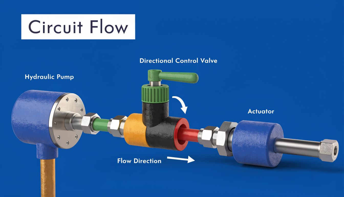
The basic flow path in operation
In a typical system, the pump draws oil from the reservoir and creates flow into the pressure line. In UK industrial equipment, many working circuits run in the 200 to 400 bar range, although the actual figure depends on actuator sizing, duty cycle, pipework losses, and the margin set at the relief valve.
The valve block directs that pressurised flow where it is needed. Shift a directional valve to extend a cylinder, and oil goes to the cap end while return oil leaves the rod end and heads back to tank. Drive a hydraulic motor, and the same circuit logic applies through the motor ports to create rotation. Pressure rises only to the level needed to move the load, plus the losses through the circuit.
That point matters in practice. Pumps create flow. Resistance to that flow creates pressure.
A basic example is a Hydronit DC power pack lifting a platform. The motor drives the pump, the pump sends oil through a manifold valve, the cylinder extends, and a relief valve protects the system if the load exceeds the set pressure. On a small industrial unit with a Vivoil gear pump, the same sequence applies, just with different flow, speed, and duty expectations.
Open-centre and closed-centre thinking
Neutral condition tells you a lot about how a circuit is intended to behave.
Open-centre layouts
In an open-centre circuit, pump flow returns to tank when the valve is in neutral. This layout is common on simpler mobile and auxiliary machinery because it is easy to service, easy to understand, and usually cost-effective.
The trade-off is continuous flow. If the machine spends long periods idling with the pump running, heat generation can become the limiting factor rather than available pressure or force. On older site and agricultural equipment, that is often where you see oil thinning out, response becoming inconsistent, and seals ageing faster than expected.
Closed-centre layouts
In a closed-centre system, flow is blocked or reduced when the valves are neutral, so supply matches demand more closely. That suits machines with multiple functions, tighter control requirements, or a need to manage power use more carefully.
It also adds complexity from an engineering perspective. Component selection, standby settings, compensator behaviour, and fault-finding all need more care. Closed-centre design earns its keep on the right machine. It is not the default answer for every application.
For UK users, that choice has a maintenance and compliance angle as well. Under the Pressure Systems Safety Regulations 2000 (PSSR), pressure risk has to be understood and controlled properly, especially where stored energy, accumulators, or poorly protected pressure lines are involved. A cleaner schematic does not remove that responsibility.
The right circuit matches the duty cycle, load pattern, control requirement, and maintenance conditions in the workshop or on site.
Why power packs simplify some applications
A self-contained hydraulic power pack brings the main parts into one assembly. Tank, electric motor, pump, manifold, valves, and relief protection are packaged together, which cuts installation time and avoids a lot of one-off pipework and bracket design.
That approach works well in lift tables, compact presses, dock equipment, machine guarding systems, and access platforms. Where space is limited, a mini pack often solves the packaging problem with fewer leak points and simpler replacement planning.
Hydronit packs are a good example. They are widely used where builders need compact DC or AC hydraulic power without designing a full centralised system from scratch. While the hardware has evolved significantly, the fundamental operating logic remains consistent. Generate flow, control direction and pressure, apply force at the actuator, then return the oil to tank.
A short visual walkthrough helps if you’re explaining circuit logic to colleagues or trainees:
What a healthy circuit looks like
A healthy hydraulic circuit has a few clear characteristics:
- Stable pressure behaviour: No unexplained spikes, drift, or valve chatter.
- Controlled temperature: Oil stays within a sensible operating range for the fluid grade and seal material.
- Clean fluid: Contamination is controlled before it reaches pumps, valves, and actuators.
- Predictable motion: Cylinders and motors move consistently, without hesitation, cavitation noise, or load instability.
When one of those is missing, the circuit is already giving you diagnostic information. Good engineers read the symptoms before ordering parts.
Hydraulics in Action Common UK Applications
Theory becomes more useful when you attach it to machines people work on every day.
In the UK, hydraulics turn up wherever loads need to be lifted, clamped, steered, pressed, tipped, or driven with controlled force. The components may differ, but the working logic stays recognisable.

Mobile machinery on farms, sites and yards
Agricultural machinery is one of the clearest examples. Tractors use hydraulic power for steering, lifting, remote services, trailers, loaders, and attached implements. A machine may combine simple spool-valve functions with more integrated power and control depending on age and application.
Construction plant uses the same core principles in a harsher environment. Excavators rely on cylinders for boom, dipper, and bucket movement. Loaders use hydraulics for lift and crowd. Telehandlers and forklifts depend on stable hydraulic motion for both productivity and operator confidence.
Materials handling is often where engineers see the importance of smooth metering and predictable response. If a lift function is jerky or drifts under load, the problem isn’t academic. It affects safety, cycle time, and operator trust immediately.
Industrial systems in production environments
Industrial hydraulics tend to look tidier than mobile hydraulics, but the engineering demands are just as real.
Presses need repeatable force. Clamping systems need stability. Power units for manufacturing cells need compact layout, sensible service access, and reliable thermal control. In recycling equipment, hydraulic cylinders and motors often work in dirty, repetitive duty where contamination control becomes central to component life.
A few common industrial uses include:
- Pressing and forming: High force in a compact footprint.
- Lifting and positioning: Controlled cylinder movement in fixtures and platforms.
- Balers and compactors: Repeated high-load cycles with a strong need for filtration discipline.
- Auxiliary machine functions: Self-contained packs powering localised motion without a plant-wide hydraulic supply.
Why hydraulics stay relevant
Engineers sometimes compare hydraulics with electromechanical alternatives as if one must replace the other everywhere.
That isn’t how real applications behave. Where force density, shock tolerance, and compact power transmission matter, hydraulics still make excellent sense. They’re especially effective when the machine must work outdoors, handle uneven loads, or survive duty that would be awkward for purely mechanical arrangements.
Good hydraulic design isn’t old-fashioned. It’s application-led.
Component Selection Maintenance and Safety Guidance
A hydraulic system rarely fails without warning. In the workshop, the usual pattern is simpler than that. The pack was underspecified for the duty, the return filtration was treated as an afterthought, the oil ran hot for months, and the eventual breakdown looked sudden only because no one acted on the early signs.
That is why component selection, maintenance, and safety have to be handled as one engineering job. A well-chosen circuit is easier to service, more stable in operation, and less likely to create a safety problem later.
Selecting components that suit the duty
Start with the load case, duty cycle, environment, and control requirement. Then choose the hardware.
For a straightforward fixed-displacement application, a gear pump is often the right answer. A Vivoil aluminium gear pump, for example, suits many compact industrial and mobile power duties where cost, simplicity, and serviceability matter more than fine proportional control. If the machine needs several functions in a small footprint, frequent starts, or an integrated motor-pump-tank package, a Hydronit power unit can be a better fit because packaging and manifold layout become part of the design decision, not an afterthought.
Selection mistakes usually come from sizing for maximum theoretical output instead of real operating behaviour. Oversized flow creates heat, noise, and unnecessary power draw. Undersized return lines raise backpressure. A tank that is too small gives the oil less time to release air and shed heat. Those are ordinary design errors, but they shorten component life quickly.
A few practical rules help keep the specification honest:
- Match pump displacement to the actual cycle: Base flow on actuator speed and duty, not on a generous guess.
- Choose valve architecture for the machine behaviour required: On-off control, load holding, shock protection, and proportional response are different jobs.
- Check the whole pressure path: Relief setting, pressure spikes, return backpressure, and hose losses all affect real system performance.
- Treat filtration as part of component protection: Pump, valve, and cylinder life depend heavily on oil cleanliness.
Maintenance that prevents the common failures
Maintenance works best when it follows likely failure modes instead of visible mess alone.
Leaks get reported first because they are easy to spot. Contamination damage often gets missed until pump noise increases, spool movement becomes erratic, or a cylinder starts creeping under load. In practice, blocked return filters, poor breather condition, and dirty top-ups cause more trouble than many teams expect.
Routine checks should cover the items that change condition in service:
- Filters and clogging indicators: Check differential indicators and change elements at the correct interval, not only after a fault.
- Fluid condition: Look for darkening, varnish, foaming, water contamination, and burnt odour.
- Hoses and fittings: Inspect for abrasion, cracked covers, twist, loose support, and small weep points around couplings.
- Pump inlet condition: Air ingress and suction restriction often show up first as noise, slow response, or aerated oil.
- Cylinder and valve behaviour: Drift, creep, stick-slip, and unequal actuator speed usually point to internal leakage or control issues.
In UK industrial service, disciplined inspection pays for itself. A blocked filter that is ignored during a planned check can become a burst seal, overheated oil, or pump damage a shift later.
Workshop note: The expensive failure gets the blame. The service item that triggered it is often much less dramatic.
UK safety and compliance
For UK operators, hydraulic safety is tied directly to statutory inspection. Systems that fall within the scope of the Pressure Systems Safety Regulations 2000 (PSSR) need a written scheme of examination where applicable, and examinations must be carried out by a competent person at the intervals set by that scheme. The HSE sets out those duties in its guidance on pressure systems at https://www.hse.gov.uk/pubns/books/l122.htm.
Examination intervals are not a universal fixed number. They depend on the system, fluid, stored energy, service conditions, and the judgement recorded in the written scheme. For that reason, it is better engineering practice to check the scheme for the installed equipment than to rely on a rule-of-thumb month range.
Enforcement also has a real cost. The HSE publishes prosecution outcomes and fines for breaches of health and safety law, including pressure-system cases, at https://www.hse.gov.uk/enforce/enforce-fees/fines.htm. For an MRO manager, the point is straightforward. Missed inspection, poor maintenance records, and degraded hydraulic hardware can become a compliance issue as well as a reliability issue.
Good practice is not complicated. Specify components for the intended duty. Keep the oil clean. Record what was inspected, changed, and tested. Make sure the maintenance plan and the written scheme support each other. That approach gives you a system that is safer, easier to troubleshoot, and less expensive to keep in service.
Conclusion Your Partner in Hydraulic Solutions
Hydraulics work because pressure in a confined fluid can be controlled and applied usefully. That basic principle leads to a complete working system made up of pumps, valves, reservoirs, filters, manifolds, motors, and cylinders.
The engineering challenge isn’t understanding the idea in the abstract. It’s making the circuit right for the duty. It’s selecting components that fit the load, the environment, and the maintenance conditions. It’s keeping the oil clean, the temperatures sensible, and the safety obligations current.
That’s why the best hydraulic systems usually aren’t the most complicated ones. They’re the ones that are well matched, well built, and well maintained.
If you’re specifying a new pack, replacing a pump, trying to cross-reference a hard-to-find component, or solving an ongoing reliability issue, experienced technical support saves time and avoids expensive guesswork.
For help with hydraulic components, compact power units, or bespoke system builds, contact MA Hydraulics Ltd. Phone 01724 279508 today, or send us a message at https://www.mahydraulics.co.uk/contact-us/
