
A lot of PTO hydraulic pump jobs start the same way. The machine itself is sound, the engine runs well, the gearbox is serviceable, but the attachment won’t perform. A loader lifts too slowly. A tipping body stalls halfway up. A grab or small crane feels hesitant under load.
That problem turns up constantly on older British machinery. Over 60% of UK tractors are over 20 years old, and many of them don’t have the remote valves or oil flow needed for newer attachments, according to the DEFRA-linked discussion referenced here. On the ground, that usually means one thing. The tractor or lorry still has life left in it, but its original hydraulic provision doesn’t match the work now being asked of it.
A properly selected pto hydraulic pump solves that mismatch. Not by guessing, and not by fitting the biggest unit you can bolt on, but by matching flow, pressure, rotation, mounting, suction conditions, and duty cycle to the job. That’s where most systems either work well for years or become a steady source of heat, noise, leaks, and broken couplings.
The Challenge of Powering Modern Hydraulic Implements
A common workshop call looks like this. An older tractor comes in to run a loader or backhoe that was added long after the machine left the factory. The operator says the attachment works, but only just. It’s slow when cold, worse when warm, and useless at idle.
On paper, the machine still has hydraulics. In practice, the built-in system often wasn’t designed for today’s attachment demands. Older tractors and mobile plant can be reliable, simple to maintain, and worth keeping in service, but hydraulic capacity is often where they show their age.
That’s why the pto hydraulic pump remains such a practical retrofit. Instead of trying to make a limited auxiliary circuit do everything, you take mechanical drive from the PTO and generate the hydraulic flow the implement needs.
Where older machines struggle
The shortfalls usually show up in a few ways:
- Low available flow: The attachment runs, but cycle times are too slow to be productive.
- Insufficient pressure under load: The ram moves until it meets resistance, then stalls or creeps.
- Too few remotes: The machine can’t practically run a modern attachment with the valve arrangement already on it.
- Excess heat: The operator holds levers open too long trying to make up for poor flow.
In UK service work, this matters because older machines are still earning their keep. They’re feeding livestock, moving grain, tipping trailers, handling pallets, and running yard equipment every week.
Fit a pump for the implement, not for the hope that “it’ll probably do”. Hydraulic systems punish wishful thinking.
Why guidance often falls short
A lot of advice online is either too generic or written for North American kit and terminology. UK engineers usually need answers to different questions. Will it suit an ageing tractor with limited space around the PTO? Can it be mounted cleanly on a plant trailer or yard lorry? Will the pump and gearbox combination give the right speed in metric flow terms, not rough guesses?
That’s the practical gap. The component itself is straightforward. Getting the whole system right is where effective system integration occurs.
What Is a PTO Hydraulic Pump and How Does It Work
A Power Take-Off, or PTO, is the machine’s mechanical power outlet. It lets the engine drive external equipment instead of only driving the wheels or transmission. When you attach a pto hydraulic pump, that rotating drive is converted into hydraulic energy by moving oil from the tank into the system at a given flow and pressure.
Think of the PTO as the machine’s standard power socket. The pump is the tool plugged into it.
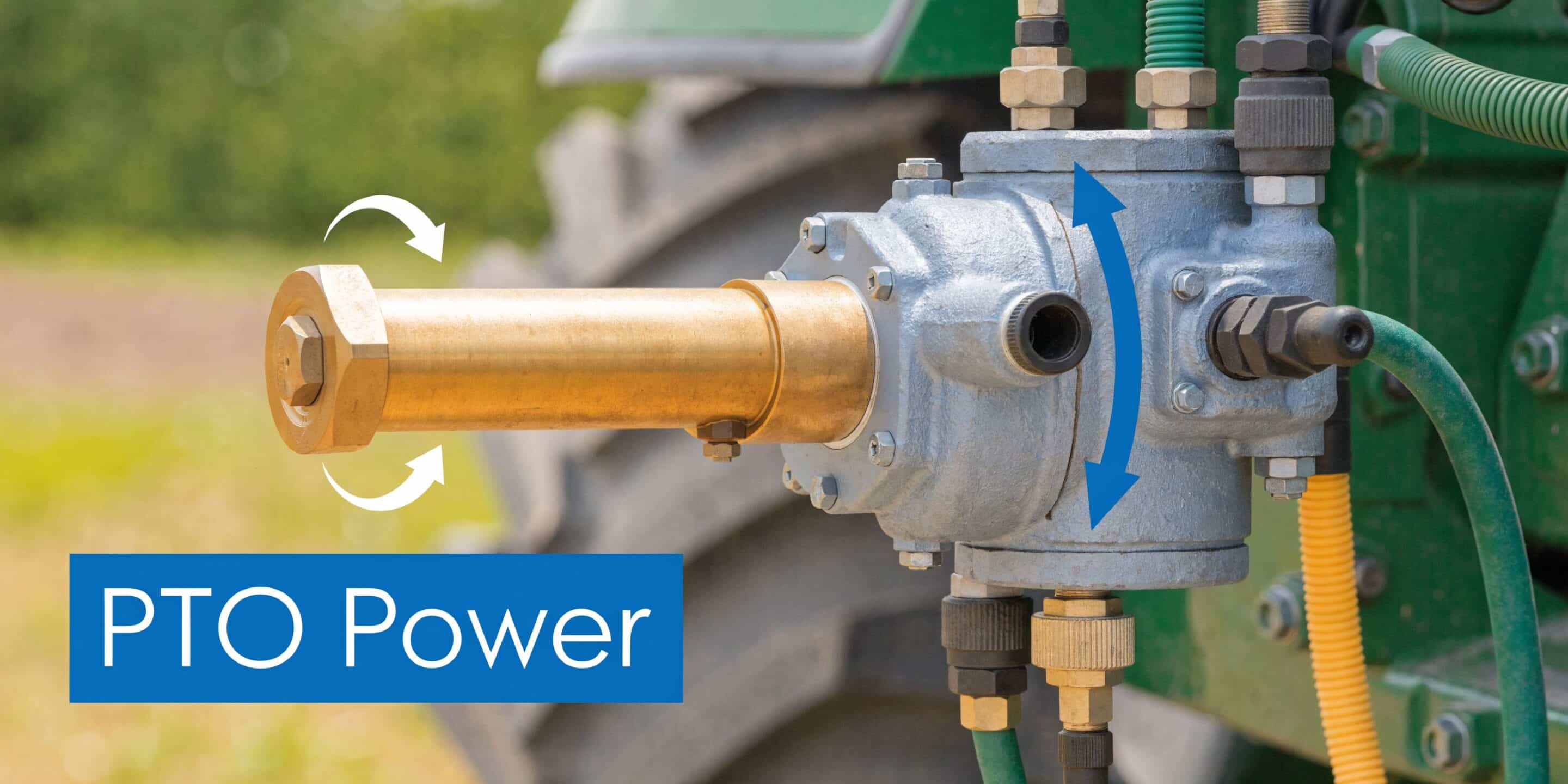
The basic operating chain
The working sequence is simple:
- The engine turns the PTO shaft
- The PTO shaft turns the pump input shaft
- The pump draws oil from the reservoir
- The pump sends pressurised oil to valves, cylinders, or motors
- Oil returns to tank and the cycle repeats
If any one part of that chain is wrong, the whole system suffers. Wrong rotation can destroy a pump quickly. A poor suction line can cause cavitation. A pump that’s too large for the available PTO power will overload the drive.
Why PTO pumps became standard on working machinery
In UK agriculture, PTO hydraulic pumps moved from useful option to standard working hardware during the post-war mechanisation push. Their adoption accelerated after the war, with standardised 540 rpm PTOs powering hydraulic pumps at flow rates up to 50 to 100 litres per minute at 200 bar, a setup that became foundational in British farming and in areas such as North Lincolnshire, as outlined in this historical overview of power take-off development.
That history still matters because many legacy machines in service today were built around those conventions. Even when the implement is modern, the PTO side often still traces back to that established 540 rpm format.
The main pump types you’ll see
Most PTO-driven mobile systems use gear pumps. There’s a reason for that. They’re compact, mechanically simple, and well suited to applications where you need dependable flow without unnecessary complexity.
Here’s the practical view:
| Pump type | Where it fits | What to watch |
|---|---|---|
| Gear pump | Trailers, loaders, tippers, sprayers, small cranes | Good general choice, but sensitive to contamination and bad suction setup |
| Piston pump | Higher-performance systems needing tighter control | More complex and usually harder to justify on straightforward mobile jobs |
| Vane pump | Smoother flow in suitable systems | Less common in many PTO retrofit jobs |
What the pump is really doing
A PTO hydraulic pump does not “make pressure” on its own in the way many operators describe it. It produces flow. Pressure appears when that flow meets resistance in the circuit, such as a loaded cylinder or hydraulic motor.
That distinction matters in fault-finding.
If a machine is slow, the first suspect is often lack of flow. If it strains or stalls under work, pressure capacity or relief valve settings usually need checking.
Why gear pumps still dominate
For practical OEM and service work, gear pumps remain the default because they do the job cleanly. Fewer moving parts. Easier cross-reference. More forgiving on straightforward systems. Better suited to the kind of agricultural and industrial fleets that need reliable parts availability rather than specialist complexity.
That doesn’t mean every gear pump suits every job. It means they’re usually the right starting point, provided the sizing and installation are done properly.
Key Specifications for Selecting the Right Pump
Choosing a pto hydraulic pump starts with the job, not the catalogue. You need to know what the attachment must do, how fast it must do it, and what the prime mover can realistically support. Once that’s clear, the pump specification becomes much easier to read properly.
Displacement and flow
Displacement is usually given in cc/rev. It tells you how much oil the pump moves for each revolution. More displacement usually means more flow at the same speed.
Modern PTO hydraulic pump displacement runs from around 56cc to 434cc, according to this pump specification reference. For practical workshop work, that range covers everything from modest trailer and auxiliary circuits up to more demanding mobile systems.
Flow rate is what the operator feels first. It affects ram speed, cycle time, and how responsive the attachment seems. If flow is too low, the system feels lazy even when pressure is available.
Pressure rating
Pressure tells you how much resistance the pump can work against safely. Here, people sometimes get caught out by housing material.
The same specification reference shows that steel housings can support pressures up to 280 bar, while typical aluminium-housed pumps are limited to about 172 bar in the cited examples. That’s not just a number on a sheet. It affects durability, case rigidity, and whether the pump is suited to sustained heavier duty.
Selection rule: Don’t choose a pump by flow alone. A unit that gives the right litres per minute but sits too close to the pressure limit won’t stay healthy for long.
Speed and input conditions
Many agricultural PTO systems are built around established shaft speeds. But the pump’s ideal working speed still has to match the drive arrangement. If the PTO speed and pump displacement aren’t aligned, you’ll either miss the target flow or force the engine to run in an awkward operating range.
Three checks matter together:
- Input speed in rpm: This determines pump output when combined with displacement.
- Direction of rotation: Clockwise and anti-clockwise mistakes are common and expensive.
- Duty cycle: A pump that survives short bursts may not suit continuous running.
Torque and power demand
Pump torque demand rises with pressure. That means a setup that seems fine when empty can overload the drive once the attachment starts real work.
For engineers doing specification work, the useful habit is to read the pump and PTO as one mechanical pair. Shaft strength, coupling condition, mounting rigidity, and gearbox rating all have to suit the actual torque demand, not just unloaded testing.
Housing material and durability
Material choice is often practical rather than academic:
- Aluminium-bodied pumps: Lighter, common on many agricultural applications, often sensible where weight and cost matter.
- Cast iron or steel-bodied pumps: Better where pressure is higher, duty is harder, or the mounting environment is less forgiving.
That’s especially relevant on mixed fleets where one machine spends half its life in the yard and the other half outdoors in poor conditions.
Ports and plumbing details
Port sizes and standards matter more than people admit. A technically correct pump can still perform badly if the inlet plumbing is restrictive or if adapters create awkward suction conditions.
Typical port arrangements in manufacturer data include SAE inlet and outlet configurations. In practice, UK installations often need careful adaptation into existing hose sets, manifolds, and reservoirs. Keep the suction side as direct and unrestricted as possible.
A quick decision view
| Specification | What it affects most | Common mistake |
|---|---|---|
| Displacement | System speed | Choosing too small and blaming the attachment |
| Pressure rating | Load capability and pump life | Running too near the limit every day |
| Speed range | Actual delivered flow | Ignoring the PTO or gearbox speed |
| Rotation | Immediate pump survival | Fitting before confirming shaft direction |
| Housing material | Strength and service life | Using light-duty construction on heavy work |
| Ports and inlet size | Suction performance | Restrictive inlet plumbing causing cavitation |
For straightforward mobile applications, a good starting point is often a gear hydraulic pump selected around real working flow and pressure rather than catalogue maximums: https://www.mahydraulics.co.uk/gear-hydraulic-pump/
Ensuring PTO Gearbox and Mounting Compatibility
A well-sized pump can still be the wrong pump if the drive side isn’t right. Most avoidable failures in PTO systems come from compatibility errors at the interface between machine, gearbox, coupling, and pump.
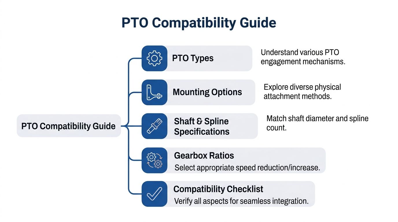
Start with the shaft and spline
Before anyone reaches for a spanner, confirm the mechanical standard you’re dealing with. On agricultural equipment, the PTO shaft format determines what can be mounted directly and what needs an intermediate gearbox or coupling arrangement.
You need to check:
- Spline count and shaft profile
- Nominal shaft speed
- Available space around the PTO
- Direction of rotation at the pump
- How the load will be supported
A direct-mount pump is tidy, but it puts more emphasis on alignment and support. A remote-mount arrangement gives more flexibility in packaging, though it adds more components that must remain aligned.
Direct mount or remote mount
There isn’t one universally correct choice.
Direct mount works well where space allows and the pump can sit cleanly on the PTO output without side loading or awkward hose routing. It keeps things compact.
Remote mount is often better where the machine layout is tight, the reservoir sits elsewhere, or the pump would otherwise be exposed to knocks, contamination, or poor hose geometry.
A compact installation isn’t automatically a durable one. If the hoses kink, the coupling runs out of line, or the pump hangs unsupported, the neat-looking setup becomes the unreliable one.
Gearbox ratios matter
The gearbox is not just an adapter. It determines the pump’s operating speed. If the ratio is wrong, the pump won’t deliver the intended flow at a sensible engine speed.
That’s where many retrofit jobs become frustrating. The operator says the pump is “too slow”, but the issue is that the selected ratio and displacement don’t suit the available PTO speed.
A sensible compatibility check includes:
- The machine’s PTO output speed
- The pump’s preferred speed range
- The required implement flow
- Whether the engine can hold that speed under load
Couplings, brackets, and fabricated mounts
Flexible couplings protect the system, but only if they’re chosen and aligned properly. A worn or incorrect spider, poor bracket stiffness, or a mounting plate that allows movement under load will quickly show up as noise, vibration, and seal wear.
Where a machine needs a custom bracket or guard, proper fabrication makes a difference. If you’re building one-off supports, guards, or mounting plates, the kind of work shown in these precision custom metal cutting services is a useful reference for how accurate cut components help with fit-up and repeatability.
For flexible drive connections, the coupling element matters as much as the metal hubs. This is the sort of component engineers often need to replace when vibration or backlash develops: https://www.mahydraulics.co.uk/spider-for-coupling/
The checks that save rework
A compatibility review should answer these questions before installation:
| Check | Why it matters |
|---|---|
| Does the shaft standard match the mounting hardware? | Prevents poor fit and damaged splines |
| Is the pump supported correctly? | Reduces casing stress and coupling wear |
| Does the gearbox ratio suit the target flow? | Avoids sluggish or oversped operation |
| Is the coupling aligned under load, not just at rest? | Stops vibration and premature seal failure |
| Can hoses be routed without strain at the pump ports? | Protects the casing and improves service life |
When these details are right, the hydraulic side becomes much easier to commission. When they’re wrong, the faults start before oil even reaches working temperature.
A Practical Guide to Installation and Commissioning
Installation quality decides whether a pto hydraulic pump gives years of service or starts leaking, whining, and overheating within weeks. The pump may be new, but the rest of the system usually isn’t. That means the installer has to assume nothing.
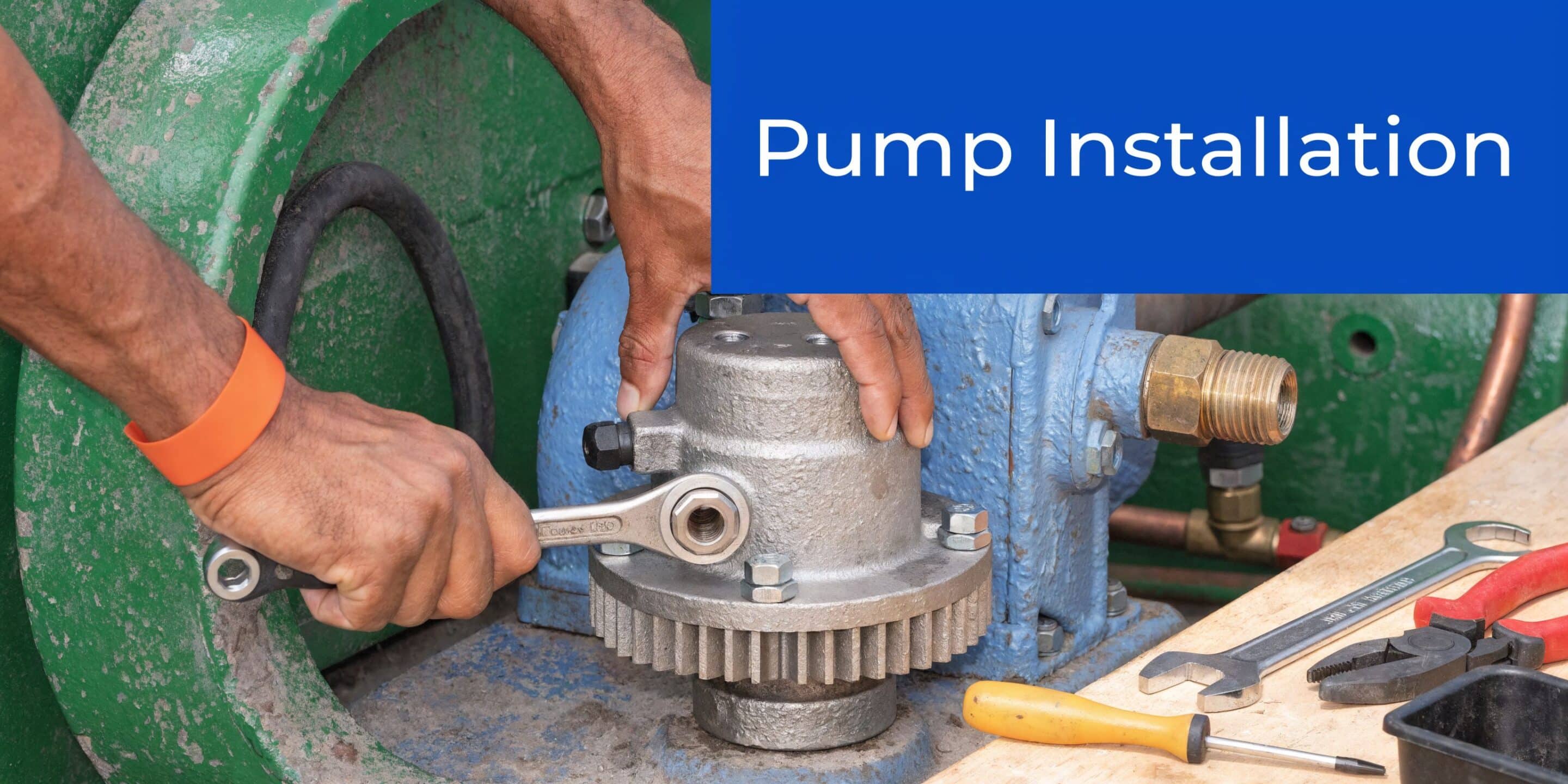
Before the pump goes anywhere near the machine
Start with basic checks that are easy to skip and expensive to ignore.
- Confirm rotation: Check the pump’s required rotation against the PTO output.
- Inspect the mounting face: Paint runs, burrs, damaged threads, and old gasket material all cause alignment issues.
- Check shaft condition: Worn splines and fretted couplings will damage the new installation.
- Look at the tank arrangement: If the reservoir is dirty or underspecified, don’t expect the new pump to survive.
If the machine has had a pump failure already, treat the whole hydraulic circuit as contaminated until proven otherwise.
Mounting and line connection
Bolt the pump squarely. Don’t draw it into position with fasteners if the coupling or flange isn’t already lining up properly. That forces the housing into stress.
Pay particular attention to the suction side. Most poor-running PTO pump systems come back to one of three causes on the inlet line:
- The hose is too restrictive
- There’s an air leak on suction
- The oil supply to the pump is poor when cold or on an incline
Pressure lines get most of the attention because they leak dramatically. Suction faults are quieter, but they ruin pumps.
Prime and protect the inlet side first. A pump can tolerate many things briefly. Running dry isn’t one of them.
Filling, priming, and first start
Fill the reservoir with the correct hydraulic fluid for the machine and application. Make sure the suction line is full and the pump is primed where the design requires it.
Then start gently:
- Run at low engine speed
- Engage the PTO smoothly
- Allow the pump to establish flow without immediate heavy loading
- Check for leaks at fittings, seals, and mounting faces
- Listen for sharp whining or rattling
- Monitor temperature rise
The first few minutes tell you a lot. A healthy system usually settles quickly. A poor one announces itself almost immediately through noise, foam, erratic movement, or a pump body that heats too fast.
A visual reference can help if you’re explaining the process to operators or junior fitters:
Commissioning under load
Once the system is leak-free and circulating properly, apply load progressively. Don’t start with the heaviest lift or full-pressure tip cycle. Build up to operating conditions.
Watch for:
| Symptom at commissioning | Likely concern |
|---|---|
| Foaming in reservoir | Air ingress on suction side |
| Harsh whining | Cavitation or restriction |
| Slow movement with normal engine speed | Incorrect displacement, low speed, or internal leakage |
| Pressure drop under load | Pump wear, relief valve issue, contaminated oil affecting components |
| Excess heat | Running over relief, viscosity problems, poor reservoir performance |
| Seal failure | Pressure spikes, misalignment, contaminated fluid, shaft movement |
What works in practice
On retrofit work, the cleanest installations usually share the same habits. The fitter keeps the inlet short, supports the pump properly, avoids unnecessary adapters, and tests at controlled load before handing the machine back.
What doesn’t work is forcing mixed components together because they nearly fit. A PTO hydraulic pump system rewards accuracy and punishes shortcuts.
Sizing Calculations and Real-World Application Examples
Most sizing mistakes come from starting with the pump instead of the task. The cylinder or motor decides the hydraulic requirement. The PTO pump is then selected to meet it within the machine’s speed and power limits.
The two core formulas are straightforward. Litres per Minute = Displacement × RPM ÷ 1000 and kW = (L/min × bar) ÷ 600, as set out in this Chelsea PTO hydraulic pump manual. That second formula matters because pressure has a direct effect on input power and heat generation.
Example one for a tipping trailer
Take a simple agricultural tipping trailer. The operator wants a faster, smoother tip than the tractor remotes can provide. The first question isn’t “which pump shall we fit?” It’s “how much flow does the tipping ram need for the target tip speed?”
Assume the trailer works acceptably with a target system flow somewhere within the commonly discussed 15 to 25 GPM range, approximately 57 to 95 L/min, which is the sort of requirement raised in UK tractor compatibility discussions linked earlier. You’d then match that target to the available PTO speed and calculate the displacement needed.
If the drive speed at the pump is known, use:
L/min = Displacement (cc/rev) × RPM ÷ 1000
So if you need a given flow, rearrange it:
Displacement = L/min × 1000 ÷ RPM
That gives a rational starting point for the pump rather than a guess based on pump body size alone.
Why moderate pressure changes everything
Now apply the power formula:
kW = (L/min × bar) ÷ 600
This aspect causes many compact systems to fail. The same flow at higher pressure demands much more from the PTO side, the engine, and the oil.
A system operating at moderate pressure is usually easier on the whole machine. It draws less power, creates less heat, and gives more margin in day-to-day use.
For a tipping body, that often means checking whether cylinder size, valve setting, and mechanical geometry are sensible before trying to “fix” performance with more pump.
Example two for a small vehicle-mounted crane
A small lorry-mounted crane is a different sort of duty. The operator wants smooth control and enough lifting performance, but the hydraulic demand is less about one simple tip stroke and more about repeatable movement under varying load.
The sizing process still follows the same order:
- Work out required actuator speed
- Determine the flow needed for that movement
- Estimate the working pressure under real load
- Calculate the required input power
- Check that the PTO drive can support it continuously
Because crane work often involves repeated motions rather than one short event, duty cycle becomes more important. A pump that looks acceptable on paper can still run too hot if it spends too much time near relief pressure.
Reading the figures properly
A few practical points matter more than the maths itself:
- Flow sets speed: If the ram is too slow, increase flow only if the rest of the system can support it.
- Pressure follows load: Don’t specify maximum pressure just because the pump can withstand it.
- Power is not free: The engine and PTO have to supply it, and the oil has to carry away the resulting heat.
For engineers wanting a clear refresher on hydraulic pressure relationships, this calculation guide is useful: https://www.mahydraulics.co.uk/how-is-pressure-calculated/
A sensible specification habit
Instead of asking “what’s the biggest PTO hydraulic pump that will fit?”, ask these:
| Better question | Why it helps |
|---|---|
| How fast does the function need to move? | Sets flow target |
| What load will it see in normal work? | Sets realistic pressure |
| How long will it run at a time? | Protects against heat and over-duty |
| What speed will the pump turn at? | Prevents wrong displacement choice |
| What can the machine drive continuously? | Stops overloading the PTO side |
That approach gives you a system that works in service, not just one that passes a bench test.
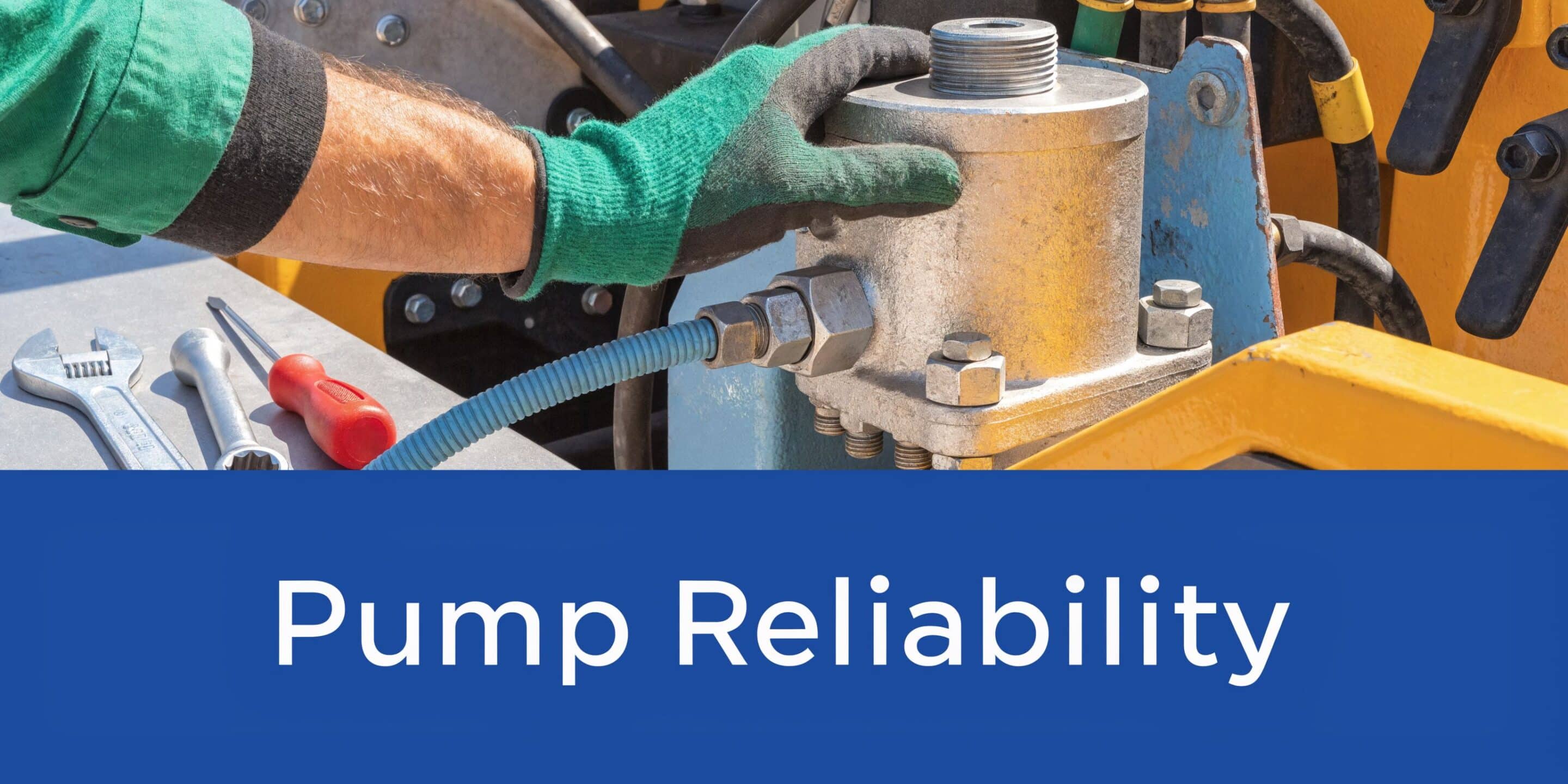
Routine Maintenance and Troubleshooting Common Failures
Most PTO pump failures don’t begin as dramatic failures. They start as small warnings. A little more noise. A slight hesitation. Oil that looks tired. A coupling that’s beginning to fret. Operators often keep using the machine because it still functions. That’s how minor faults become expensive ones.
The biggest maintenance lesson is simple. Keep the oil clean, keep the inlet side healthy, and pay attention to early symptoms.
Contamination is the first thing to control
According to data cited from the UK Road Haulage Association, 28% of heavy-duty truck PTO failures are due to contamination from poor fluid quality in wet climates, and early signs such as whining or pressure drops can come before debris damage that costs over £2,500 per incident to repair, as summarised in this PTO pump failure reference.
That aligns with what service engineers see every week. Water ingress, dirty reservoirs, neglected breathers, and filter changes left too long all shorten pump life quickly.
A practical maintenance routine
Good maintenance doesn’t have to be complicated. It does have to be consistent.
Daily or pre-use checks
- Look for leaks: Shaft seal dampness, weeping fittings, and fresh oil trails all matter.
- Listen on engagement: New whining, rattling, or chatter means investigate before continuing.
- Check oil level and appearance: Milky oil, foam, or visible debris are warning signs.
Regular workshop checks
- Inspect suction hoses: Soft walls, flattened bends, and poor clamps cause inlet problems.
- Clean or replace filters as required: Don’t fit a new pump into an old contaminated circuit.
- Check coupling condition: Wear in the spider or hubs often appears before larger failures.
Periodic system review
A proper service interval should include oil condition, breather condition, valve behaviour, and reservoir cleanliness. On mixed fleets, this matters even more because machines often sit idle, work in wet yards, and then return to heavy use without much middle ground.
If the pump is getting louder, the system is already telling you something. Pumps rarely “heal” by carrying on.
Common symptoms and likely causes
| Symptom | Usual cause |
|---|---|
| High-pitched whine | Cavitation, restricted inlet, air leak, low oil supply |
| Slow operation | Low flow, worn pump, low speed, internal leakage |
| Pressure drop under load | Pump wear, relief valve issue, contaminated oil affecting components |
| Excess heat | Running over relief, viscosity problems, poor reservoir performance |
| Seal failure | Pressure spikes, misalignment, contaminated fluid, shaft movement |
Fault-finding in the right order
When a PTO hydraulic pump underperforms, test logically.
Start at the tank. Then the suction line. Then the pump drive and rotation. Then pressure settings and valve behaviour. Too many repairs begin at the pump because it’s the obvious component, even when the fault sits upstream in the inlet arrangement or downstream at the relief valve.
A practical diagnostic order is:
- Verify fluid level and fluid condition
- Inspect suction line integrity
- Confirm pump speed and rotation
- Check for coupling or mounting movement
- Measure system pressure under load
- Assess whether heat build-up points to bypassing or restriction
What prevents repeat failures
Effective repair involves not just replacing the failed part. It’s removing the cause.
If contamination killed the old pump, flush the system and address the reservoir and filtration. If the coupling failed, check alignment and support. If the pump whined from day one, revisit the inlet design and reservoir arrangement.
That’s the difference between repair and resolution. One gets the machine moving again. The other stops it coming back with the same problem.
Your Partner for PTO Hydraulic Solutions
A pto hydraulic pump only performs as well as the system around it. Correct sizing, proper gearbox and mounting compatibility, clean installation, and disciplined maintenance all matter. Ignore one of those and the faults usually appear quickly.
For OEM builds, retrofits, and service work on Britain’s ageing agricultural and industrial fleet, the best results come from matching the pump to the specific job rather than forcing a near-enough solution into place. That applies whether you’re dealing with a tipper, loader, sprayer, yard machine, or lorry-mounted equipment.
If you need help with component selection, cross-referencing, or a practical hydraulic solution for your machine, contact MA Hydraulics Ltd. Phone 01724 279508 today, or send us a message at https://www.mahydraulics.co.uk/contact-us/
