
A gauge is climbing on a small hydraulic circuit, the pump is still running, and the operator is unsure whether an 8 bar pressure relief valve will protect the system or bypass oil all day. That uncertainty is common because 8 bar looks like a product rating, yet it's really a calibration point chosen in relation to working pressure, flow, component limits and the valve's behaviour under load.
In a well-designed low-pressure circuit, the valve stays closed during normal operation. If a blocked orifice, stalled actuator or dead-headed pump pushes pressure beyond the selected threshold, the valve opens and diverts fluid safely. The important question isn't only whether a valve is marked “8 bar”. It's whether it opens at the right pressure, passes the complete pump flow and fits the UK compliance and maintenance requirements of the installation.
Why 8 Bar Matters in Real Hydraulic Systems
A technician notices a gauge moving past 7 bar on a clamping circuit. The relief valve begins to hiss, the cylinder stops tightening, and the pressure settles rather than continuing towards the hose or seal limit. Nothing dramatic happens, which is exactly what the protection system was designed to achieve.
An 8 bar setpoint is deliberate. It can suit low-pressure duties such as light clamping, lubrication loops, test rigs and return-line protection, where a higher-pressure circuit would add unnecessary stress, noise and component cost. UK hydraulic suppliers list relief valves across much wider pressure bands, including low-pressure units around 10 bar and high-pressure products reaching 80–300 bar, so 8 bar belongs at the low end of hydraulic control rather than representing a universal industrial setting. See the UK hydraulic relief-valve range for the breadth of pressure bands available.
The setpoint sits inside a safety architecture
A practical UK rule is to set a relief valve slightly above maximum working pressure, commonly 10–15% higher, so it won't open during ordinary duty while still protecting the weakest component during an overpressure event. That relationship is explained in hydraulic pressure relief valve guidance, which also describes gradual adjustment while monitoring a gauge.
The valve must also pass the full pump flow when it lifts. A valve that cracks at 8 bar but cannot discharge the pump's output can leave pressure rising while the operator assumes the system is protected. The same issue applies to a blocked orifice, a stuck actuator or a hose failure that changes the circuit's flow path.
Practical rule: An undersized or incorrectly adjusted relief valve can make the valve itself the weakest link in an otherwise sound hydraulic circuit.
In UK building-services and domestic hot-water work, 8 bar is also a recognised protection point. Manufacturer documentation commonly shows 8.0 bar relief valves alongside 3 bar pressure-reducing valves, while UK guidance places pressure relief settings in the 6–8 bar range for these systems. The wider safety framework applies above 0.5 bar gauge, and BS EN ISO 4126:2019 covers safety-valve design and testing from set pressures of 0.1 bar gauge upwards, as summarised in the technical documentation for unvented-cylinder protection.
How a Pressure Relief Valve Actually Works
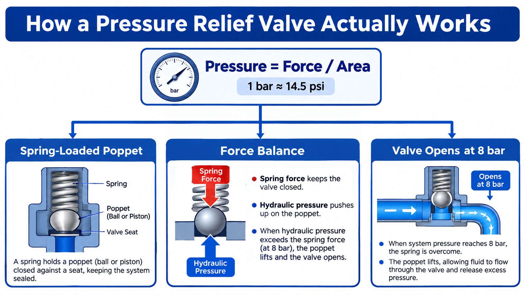
Start with the unit on the gauge. Bar describes pressure, which is force applied over an area. For rough imperial conversion, 1 bar is approximately 14.5 psi, a relationship shown in the required pressure relief valve infographic. On a hydraulic gauge, though, bar is normally the practical unit used for setting and checking the circuit.
Inside a conventional direct-acting valve, hydraulic pressure pushes against a poppet, ball or spool. A spring pushes in the opposite direction. While spring force is greater, the valve remains shut and the pump flow continues towards the actuator. As pressure rises, the hydraulic force increases until it overcomes the spring preload.
A kitchen tap with a strong spring provides a useful comparison. Water pressure can push against the valve, but the spring holds the sealing element closed until the pressure and force are high enough to move it. A hydraulic relief valve performs the same basic balancing act, but it returns oil to tank or another safe low-pressure path rather than allowing pressure to keep building.
Four terms buyers often confuse
- Cracking pressure is the point at which the valve first begins to open. Fluid may only pass in a small quantity at this stage.
- Set pressure is the selected operating threshold used for the relief function. Depending on the valve design and test method, the stated setpoint must be understood alongside its flow conditions.
- Adjustment range is the band over which the spring can be tuned. A valve needs an adjustment range that includes 8 bar, not merely a nominal label.
- Reseat pressure is the pressure at which the valve closes again as system pressure falls. A valve can open correctly yet reseat poorly if the seat is worn, contaminated or affected by unstable flow.
Dampening orifices, pilot stages and carefully designed flow paths help reduce chatter, the rapid opening and closing that can damage seats and generate noise. The exact reseat behaviour depends on the construction, but the practical objective is consistent. The valve should open decisively during an overpressure event and close cleanly once pressure returns to a safe level.
For an 8 bar application, don't assume “8 bar” describes every stage of that movement. Ask whether the supplier specifies cracking pressure, full-flow set pressure, adjustment range and reseat performance.
Where an 8 Bar Setpoint Fits in Hydraulic Practice
An 8 bar circuit has a specific job. It isn't a substitute for the high-pressure hydraulics used on a machine tool, press or mobile transmission. It's better suited to systems where modest force is sufficient and where a low-pressure relief path protects smaller pumps, seals, hoses and actuators.
Typical duties include clamping fixtures on machining centres, lubrication circuits, oil-skimmer return protection, hydraulic test benches, small jacking systems and pilot supplies for larger valves. In these applications, a carefully selected low-pressure valve can protect the circuit without forcing every component to tolerate a much higher operating pressure.
| Pressure Band | Typical Setpoint | Typical Use | Example Components |
|---|---|---|---|
| Low-pressure circuit | 8 bar | Light clamping, lubrication and pilot duties | Small pump, direct-acting relief valve, compact cylinder |
| Mid-pressure industrial circuit | 180–210 bar | General machine hydraulics | Industrial power unit, directional valve, actuator |
| High-pressure mobile or press circuit | 350 bar and above | Mobile equipment and pressing duties | High-pressure pump, manifold, high-rated hose and cylinder |
The mid- and high-pressure figures in the comparison reflect the pressure stages described in UK hydraulic supplier data, including catalogue ranges covering 105, 210 and 350 bar. HydraForce valve certification data illustrates why the spring range and construction matter when selecting a calibration point.
Match the setpoint to the working pressure
Suppose a circuit normally works between 6 and 7 bar, while the pump can produce more pressure than the actuator should receive. An 8 bar relief valve can provide a sensible upper limit, provided the hoses, seals, actuator and manifold are suitable for the resulting pressure. Don't use the figure in isolation. Check the maximum working pressure of every pressure-containing component and confirm the valve can handle the pump's flow.
UK potable-water approvals also show that 8 bar can be a documented approval point rather than an arbitrary nominal figure. WRAS-listed assemblies include relief valves pre-set at 6.0 or 8.0 bar, some with an adjustment band from 8.3 bar to 10.2 bar, and some with a maximum operating pressure of 16.0 bar, as shown in the WRAS approvals directory. Those values describe particular approved assemblies, not a licence to apply one valve across unrelated hydraulic duties.
Choosing the Right 8 Bar Pressure Relief Valve
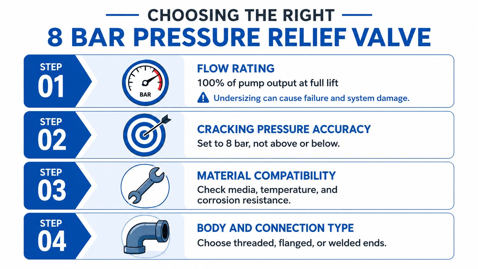
Selection should start with flow, not the sticker on the spring adjuster. A valve must pass the pump's complete output when it reaches full lift. Product listings commonly publish maximum flow, pressure range and thread size together, which is a useful reminder that pressure alone doesn't describe performance. A pressure relief valve sizing guide can help organise the calculation before you compare individual models.
Four decisions determine suitability
First, confirm flow capacity. If the pump delivers more flow than the valve can discharge, pressure can continue rising even though the valve has started to open. Check the manufacturer's flow curve or full-lift capacity rather than relying on the nominal port size.
Next, match the connection. Identify whether the circuit uses BSPP, BSPT, NPT, SAE or another thread standard. UK hydraulic systems commonly use BSP formats, but imported pumps and manifolds may use different connections. A reducer can solve a thread mismatch, yet it may also restrict the flow path and create extra turbulence.
Then examine the opening behaviour. A direct-acting poppet valve is straightforward and suits low-flow circuits. As flow increases, a pilot-operated or two-stage design can provide a more controlled lift and pressure rise. The right choice depends on pump output, duty cycle, noise limits and the stability of the circuit.
Finally, choose the body material. Carbon steel is a practical option for general mineral-oil service. Stainless steel or zinc-nickel-plated construction can suit washdown, marine or corrosive surroundings. Brass may suit a lower-cost OEM assembly where the fluid, pressure and environmental conditions are compatible.
The adjustment range should include 8 bar with useful headroom either side, so the spring isn't operating at the extreme end of its travel. UK technical data for one safety-relief series shows an adjustment range of 2.5–8 bar and a 10 bar static limit across different connection formats and body styles, demonstrating why the setpoint must be considered alongside the valve's adjustment and body limits. Review the 8 bar safety relief valve series for the relationship between setpoint, connection and construction.
A locknut and tamper-resistant cap are worthwhile where operators or maintenance staff could alter the setting accidentally. Record the selected pressure, fluid, temperature and flow requirement on the purchase specification.
Comparing Valve Types at the 8 Bar Level
Three valve families can all be supplied around an 8 bar setting, but they don't respond identically. The choice should follow flow, available manifold space, contamination risk and how often the valve is expected to relieve.
A direct-acting poppet or spool valve uses the main circuit pressure directly against its spring. It's simple, compact and a good fit for small hand-pump units, clamping fixtures and lubrication loops. It generally suits lower-flow applications, particularly where a little pressure variation during opening won't affect the process.
A pilot-operated valve uses a small pilot stage to control a larger main stage. That arrangement can give a smoother pressure rise, lower noise and more predictable reseating when a power unit handles substantial flow. It adds internal complexity, so clean fluid and correct installation become more important.
A cartridge valve screws into a prepared manifold cavity. It saves plumbing space and can make a compact mobile or OEM assembly easier to service, but the manifold must be machined correctly and the cartridge must match the cavity specification.
| Type | Typical Flow Range | Cost | Best 8 Bar Application |
|---|---|---|---|
| Direct-acting | Under 20 l/min | Lower | Small pumps, clamping fixtures and lubrication loops |
| Pilot-operated | 40–150 l/min | Higher | Larger hydraulic power units needing smoother relief |
| Cartridge | Application-dependent | Varies | Compact mobile equipment and manifold blocks |
The flow examples above reflect the practical distinctions in the supplied design guidance. They shouldn't replace the manufacturer's flow curve. A direct-acting valve can be an excellent choice when the circuit is small and uncomplicated, while a pilot-operated valve becomes more attractive when bypass flow, heat generation and noise need tighter control.
A cartridge solution is less about the pressure number and more about packaging. If the manifold already has a suitable cavity, it can remove external pipework. If it doesn't, the machining and replacement requirements may outweigh the space saving.
Installing and Adjusting an 8 Bar Relief Valve
Commissioning should be controlled, measured and recorded. Adjustment by feel is not enough because the spring position, oil temperature, gauge accuracy and flow condition all affect what the operator sees.
Use a measured commissioning sequence
-
Isolate and depressurise the circuit. Stop the pump, secure the energy source and confirm that stored pressure has dissipated. Mount the valve as close to the pump discharge as practical, because pipe and hose pressure loss can make the pressure at the valve differ from the pressure at the actuator.
-
Fit a suitable test gauge. Use a calibrated gauge covering the expected pressure range, connected to a dedicated test port rather than relying only on a remote system gauge. The gauge should be readable enough to distinguish the intended setpoint from normal fluctuation.
-
Run the pump carefully. With the cylinder unloaded, start the pump and adjust gradually while watching the gauge. Bring the circuit to the target setting under a controlled dead-head condition, following the valve manufacturer's procedure.
-
Check relief and reseating. Operate a downstream actuator so flow resumes, then allow the circuit to return to the relief condition. Confirm that the valve opens as intended and closes without persistent hissing, pressure instability or excessive heat generation.
-
Lock and document the setting. Tighten the locknut, fit a tamper-resistant cap where appropriate and record the setpoint, gauge identification, date, fluid and any observed flow condition on the commissioning sheet.
A valve shouldn't be adjusted above the component design limits to cure slow actuator movement. If the circuit needs more pressure, review the pump, actuator area, load and control valve rather than defeating the safety function.
Use a documented pressure monitoring system where the application needs continuous visibility rather than an occasional commissioning check. The monitoring arrangement should show where pressure is measured and which component provides the final relief path.
Maintenance, Testing and Common Failure Signs
A relief valve can remain untouched for a long time, then become the most important component in the circuit during a single blocked-flow event. Build testing into planned maintenance rather than waiting for a hose, seal or pump problem to reveal that the valve has degraded.
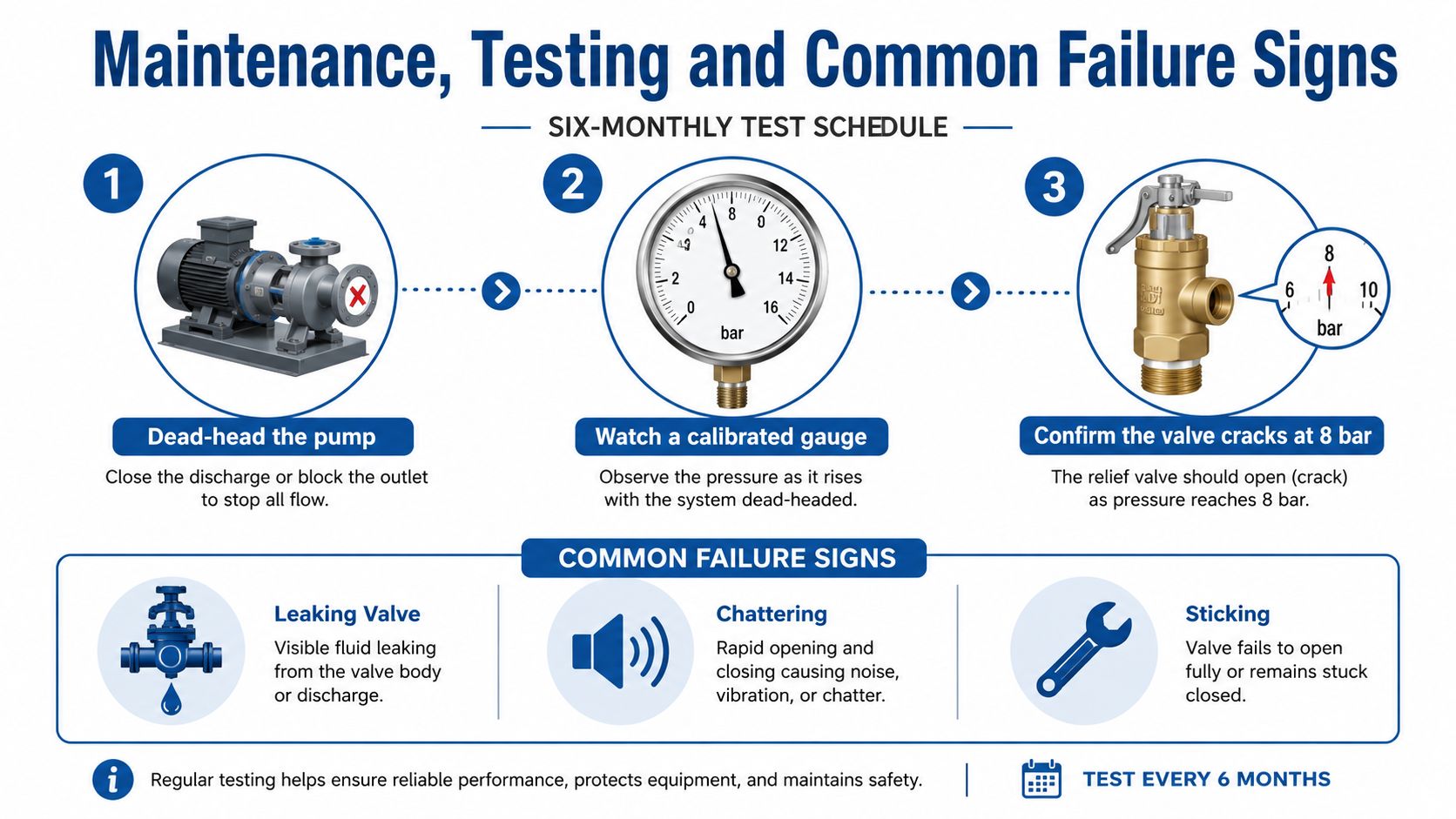
A practical schedule is to test the valve every six months. During the test, dead-head the pump under controlled conditions, observe a calibrated gauge, confirm the valve opens within ±5% of the 8 bar setpoint, and check that it reseats when pressure falls. This tolerance is part of the supplied maintenance guidance and should be applied only where it matches the equipment manufacturer's testing requirements.
Read the symptoms correctly
- Set too high: The valve doesn't relieve when expected. A hose may bulge, a seal may leak or the pump may sound strained.
- Set too low: The valve bypasses during normal work. Oil heats up, the actuator loses force and the pump spends its time pushing fluid across the relief path.
- Sticking mid-stroke: Pressure may rise beyond the expected point while the circuit performs poorly. Contamination, varnish, damaged springs and worn seats can all contribute.
- Chatter or persistent hiss: A worn seat, unstable flow or contaminated pilot stage can prevent clean opening and reseating. Listen at the tank line, but don't place hands near a suspected leak.
Keep a logbook containing the setpoint, observed full-lift flow and reseat pressure. Isolate the actuator circuit before manual adjustment because cylinders and accumulators can retain stored energy even after the pump stops.
A relief valve that opens is not necessarily a healthy relief valve. It must open at the correct pressure, pass the required flow and close without repeated oscillation.
The supplied maintenance video can support visual training, but it shouldn't replace the machine's risk assessment or the valve manufacturer's procedure.
UK Standards, Sourcing and Next Steps
In UK building-services and domestic-hot-water installations, an 8 bar relief valve forms part of a wider safety arrangement rather than acting as an isolated accessory. The supplied technical documentation describes the historical move away from withdrawn BS 6759 towards harmonised European and UK standards, with BS EN ISO 4126:2019 now used for safety-valve design and testing. The Pressure Equipment (Safety) Regulations 2016 apply to systems above 0.5 bar, making pressure-relief selection a formal engineering and compliance matter.
For hydraulic machinery, identify which regulations and examination requirements apply to the complete installation. The Pressure Systems Safety Regulations 2000 may be relevant to pressure systems and stored-energy equipment, while machinery electrical safety and work-equipment duties may also affect the wider design. Don't assume that a valve's approval automatically certifies the complete machine.
Put these details on the purchase order
- Maximum working pressure: Confirm the body and connected components can tolerate the intended pressure, including the relevant proof or test information.
- Full pump flow: Ask for the valve's capacity at full lift, not the cracking pressure.
- Port and thread: State the required BSPP, BSPT, SAE or other connection format, together with the physical port size.
- Fluid and material: Specify mineral oil, water or another medium, then check seals, body material and temperature suitability.
- Traceability: Request the manufacturer's data, setting information and any approval or certification relevant to the installation.
UK technical listings show that WRAS-approved relief valves can be supplied at 6.0 or 8.0 bar, with particular assemblies also showing 8.3–10.2 bar adjustment and a 16.0 bar maximum operating pressure. Those figures belong to the listed products, so buyers should verify the exact model rather than treating them as universal limits.
A clear specification makes sourcing much easier. Use compliance verification support to check that the selected component, connection, pressure band and documentation align with the intended installation. MA Hydraulics Ltd can also help buyers compare hydraulic relief valves, modular valve options and complete power-unit requirements against the actual pump flow and working pressure.
MA Hydraulics Ltd can help you select an 8 bar pressure relief valve, verify flow and connection requirements, and source suitable hydraulic components or bespoke power solutions. Visit MA Hydraulics Ltd, phone 01724 279508 today, or send us a message with your pump flow, working pressure and port details.
