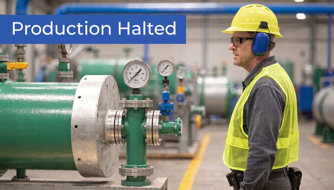
At some point, most compressed air problems look like machine problems.
A cylinder slows down. A knife gate stops short. A packaging line starts faulting only during the busiest part of the shift. Maintenance changes a valve, then a regulator, then a solenoid. The fault comes back because the actual issue sits upstream in the pipework.
That’s why compressor air piping deserves engineering attention, not leftover attention. In UK factories, workshops, agricultural installations and mobile hydraulic systems, the pipe network decides whether the air supply arrives clean, dry and stable, or turns into a constant source of pressure loss, moisture trouble and downtime.
Why Your Compressor Air Piping Is a Critical Asset
A lot of systems are built as if the compressor is the asset and the piping is just plumbing. That’s backwards.
If the furthest actuator sees a pressure dip in the middle of production, the line doesn’t care that the compressor itself is healthy. What matters is delivered air at the point of use. Badly routed mains, undersized branches, poor drainage and tired fittings will undermine the whole installation.
Downtime often starts in the distribution network
The common pattern is familiar.
A site adds one more machine. Then another drop line. Then a quick tee into an existing branch. Nobody revisits the main header size, moisture separation or isolation strategy. Months later, operators report intermittent faults that only happen under peak demand.
That’s not unusual. It’s what happens when compressor air piping grows in patches instead of being designed as a working utility.
Practical rule: If a pneumatic problem appears only when several consumers run together, inspect the distribution layout before blaming the end device.
Compressed air has been proving its value for a long time. The industrial use of piped compressed air for power transmission was proven in 1861 during the Mont Cenis Tunnel construction, where a 600 kPa compressed air plant powered pneumatic drills over long distances without the pressure loss seen with steam, helping establish compressed air as a reliable industrial utility (compressed air history).
Treat it like a utility, not an accessory
That historical lesson still matters. Compressed air works well when the delivery system is reliable.
On site, that means the pipework has to do four jobs at once:
- Carry volume without choking flow
- Hold pressure without excessive loss
- Keep condensate away from tools and controls
- Allow safe maintenance and future expansion
If any one of those jobs is neglected, the rest of the system starts compensating. People raise set pressure. They fit bigger compressors. They replace components that weren’t faulty in the first place.
That’s expensive, and it usually doesn’t solve the root cause.
Where this matters most
The consequences are sharper in systems that combine pneumatics and hydraulics.
A mobile machine, a power pack installation, or an agricultural system often has limited space, vibration, outdoor exposure and periods of heavy demand. In those environments, a poor pipe run won’t stay a minor issue for long. It becomes erratic operation, water contamination, cracked fittings, or a callout nobody wanted.
Good compressor air piping isn’t glamorous. It is, however, one of the clearest separators between a system that behaves predictably and one that never quite does.
Laying the Groundwork Your System Layout and Demand
Before buying pipe, map the air demand properly.
Most costly mistakes happen before installation starts. Once the pipe is in, people tend to defend it, work around it and patch it. A few hours spent auditing the load is far cheaper than years of living with the wrong layout.
Start with every point of use
List every consumer, not just the obvious ones.
Include production equipment, blow-off points, actuators, air tools, purge lines, control panels, cylinder circuits, maintenance outlets and any future machine positions that are already likely. In mixed hydraulic and pneumatic systems, don’t forget ancillaries such as control air for valve functions or auxiliary pneumatic devices mounted near the power pack.
For each point, record:
- Required operating pressure at the machine, not just compressor discharge pressure
- Expected flow demand from the equipment data
- Duty pattern, meaning steady use, intermittent use or short sharp peaks
- Criticality, which tells you what must keep running if a branch is isolated
If the data sheet is vague, observe the machine during operation. That tells you more than a nominal catalogue figure.
Average load doesn’t size a system
A plant can run happily all morning and still be wrongly sized.
What matters in compressor air piping is not just average use. It’s the peak combined demand when several consumers operate together. That’s when pressure drop shows itself and the complaints begin.
The disciplined approach is to separate the load into groups:
- Continuous consumers such as control air or permanent process demand
- Intermittent consumers such as cylinders and tool stations
- Short-duration peaks such as blow-off or cleaning nozzles
- Occasional maintenance demand that people forget until shutdown work begins
If two high-demand devices never operate together, don’t size the main as if they do. If they can run together under production conditions, assume they will.
The best layouts are built around real operating patterns, not catalogue assumptions.
Draw the route before you cost the parts
A quick sketch often exposes design problems early.
Mark compressor location, receiver, dryer, filters, main headers, drop legs, drains, isolation valves and future branches. Then walk the route physically. Ceiling obstacles, doorways, heat sources, washdown areas and vehicle movement all matter.
On larger sites, estimating tools used in adjacent building services disciplines can help structure the planning stage. Something like HVAC estimating software can be useful for route visualisation, material take-off thinking and identifying where long runs or awkward offsets will add complexity, even though compressed air still needs its own engineering checks.
Ring main or dead-end line
For most industrial buildings, a looped main is the better answer.
A ring main feeds demand from more than one direction, which helps equalise pressure and gives you more flexibility when one part of the system is isolated. A simple linear run can work on small installations, but it becomes less forgiving as demand grows or branches multiply.
A quick comparison helps.
| Layout | Where it works | Main advantage | Main drawback |
|---|---|---|---|
| Linear run | Small workshops, short distances, few outlets | Simple and lower initial complexity | Pressure falls away more sharply as distance and demand increase |
| Ring main | Larger buildings, multiple machine groups, staged expansion | More even supply and better resilience during maintenance | Needs better planning and more pipework |
| Hybrid layout | Mixed facilities with one dominant process area | Balances cost with performance | Easy to get wrong if branches are added casually |
Leave room for expansion, but don’t guess wildly
Futureproofing doesn’t mean oversupplying everything.
It means leaving sensible branch points, using accessible isolation valves, and allowing physical space for dryers, filters or extra drops later. It also means documenting what each branch serves so the next person doesn’t cut into the wrong line on a Friday afternoon.
In mobile and agricultural applications, planning matters even more because rerouting later is usually awkward. Bodywork, guards, tank mounts and hose movement limit your choices. A clean initial layout prevents years of compromise.
Selecting the Right Piping Materials and Components
A system that looks tidy on install day can still become expensive to live with.
The wrong pipe material sheds contamination, traps you into awkward modifications, or starts leaking after a few winters in a UK yard. I have seen all three. In industrial plants and on mobile hydraulic equipment, material choice affects pressure stability, air quality, maintenance time, and whether a repair is a short shutdown or half a day lost.
What a good material must do
Start with the duty, not with habit.
Compressed air pipework in the UK has to cope with condensate, temperature swings, plant traffic, and the practical realities of inspection and repair under BCAS good practice and PSSR 2000 responsibilities. That means the material needs to hold pressure safely, resist internal corrosion, keep a clean bore, and remain serviceable years later when someone needs to add a branch or replace a damaged section.
Long service life matters, but so does how the system fails. A material that corrodes internally can contaminate tools and valves long before it leaks. A material that dents easily may be fine in a clean factory but a poor choice beside fork trucks or on mobile equipment exposed to vibration and impact.
Historical large-scale compressed air infrastructure proves the value of durable design. The Paris network that regulated 8,000 clocks through 65 kilometres of underground mains and late 19th-century hydraulic air compressors that achieved up to 8 bar and 3,000 kilowatts showed that strong distribution infrastructure could remain dependable over long periods (history of the compressed air economy).
Material comparison in practice
| Material | Strengths | Weaknesses | Best fit |
|---|---|---|---|
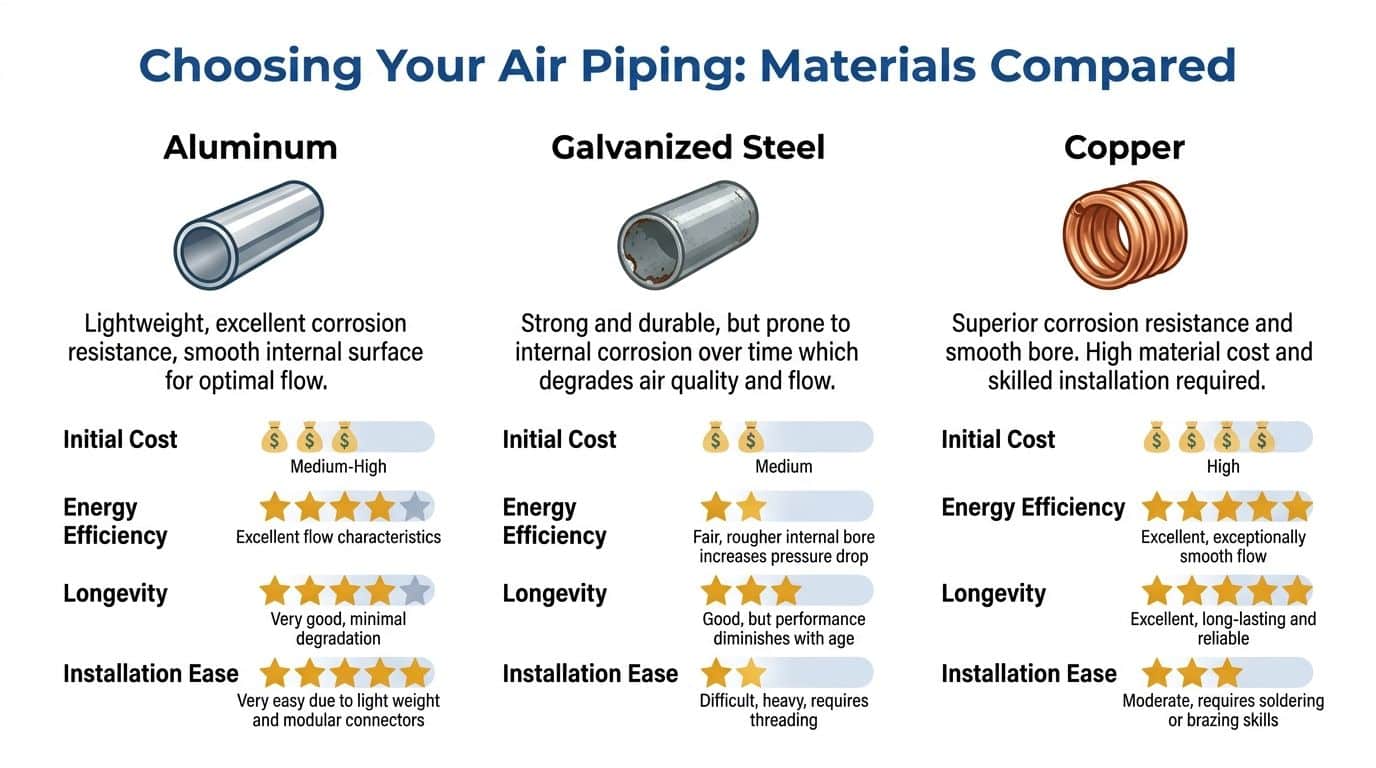
| Aluminium | Light, smooth bore, corrosion resistant, fast to install with modular fittings | Can be damaged if left exposed, joint quality and support spacing matter | Factory retrofits, clean indoor routes, projects where downtime during installation must be kept short |
| Galvanised steel | Strong, familiar, structurally sound, good resistance to accidental knocks | Heavy, slower to alter, internal corrosion can become a problem over time | Older plant rooms, impact-prone areas, sections where physical abuse is more likely |
| Stainless steel | Excellent corrosion resistance, strong, well suited to wet or aggressive environments | Higher material and fabrication cost, slower installation than modular systems | Food-adjacent zones, washdown areas, outdoor duty, mobile or coastal applications |
| Copper | Smooth internal surface, corrosion resistant, tidy for smaller systems | Material cost and skilled joining can limit where it makes sense | Smaller high-quality installations and specialist applications |
What actually drives the choice
Aluminium earns its place on many retrofit jobs because it installs quickly and keeps a clean internal surface. That matters when a site cannot afford a long shutdown and wants a system that is easy to extend later. It is often a sensible choice for indoor industrial work where routes are protected and the installers follow the manufacturer’s jointing and support details properly.
It is not the default answer for every site.
If pipework runs low across service bays, through loading areas, or around mobile hydraulic machinery, impact resistance becomes more important. In those cases, galvanised steel or stainless steel may justify the extra labour. Stainless is often the safer long-term decision where there is regular washdown, persistent moisture, fertiliser exposure, road salt, or outdoor mounting on plant and agricultural equipment.
Copper still has a place, especially on smaller systems where neat installation and clean bore matter more than lowest first cost. It is less forgiving on labour and material price, so it tends to suit specialist applications rather than large distribution networks.
Support hardware matters as well. A good pipe material can still give poor service if clips, brackets, and auxiliary fixings corrode or loosen under vibration. Where small-bore auxiliary lines need securing, especially on mobile or vibrating assemblies, stainless steel worm clamps for vibration-prone line support are usually a better choice than mild steel clips that rust and lose tension.
Choose materials for the environment, access conditions, and maintenance reality of the site.
Components that decide whether the system stays reliable
Pipe choice gets most of the attention, but failures usually start at fittings, valves, drains, and take-offs.
Use full-bore isolation valves so maintenance can be carried out without turning the valve itself into a restriction. Be selective with push-fit systems. Good ones work well when the pipe is cut cleanly, inserted fully, and supported correctly. Poor fittings, mixed systems, or rushed assembly create leak paths that can cause money to leak away for years.
Take-offs and drops need the same discipline. Poor branch geometry carries condensate into the line serving the equipment. Low points without drains become water traps. FRL units should match the duty of the downstream machine, not be fitted as a standard pack everywhere because it looks complete.
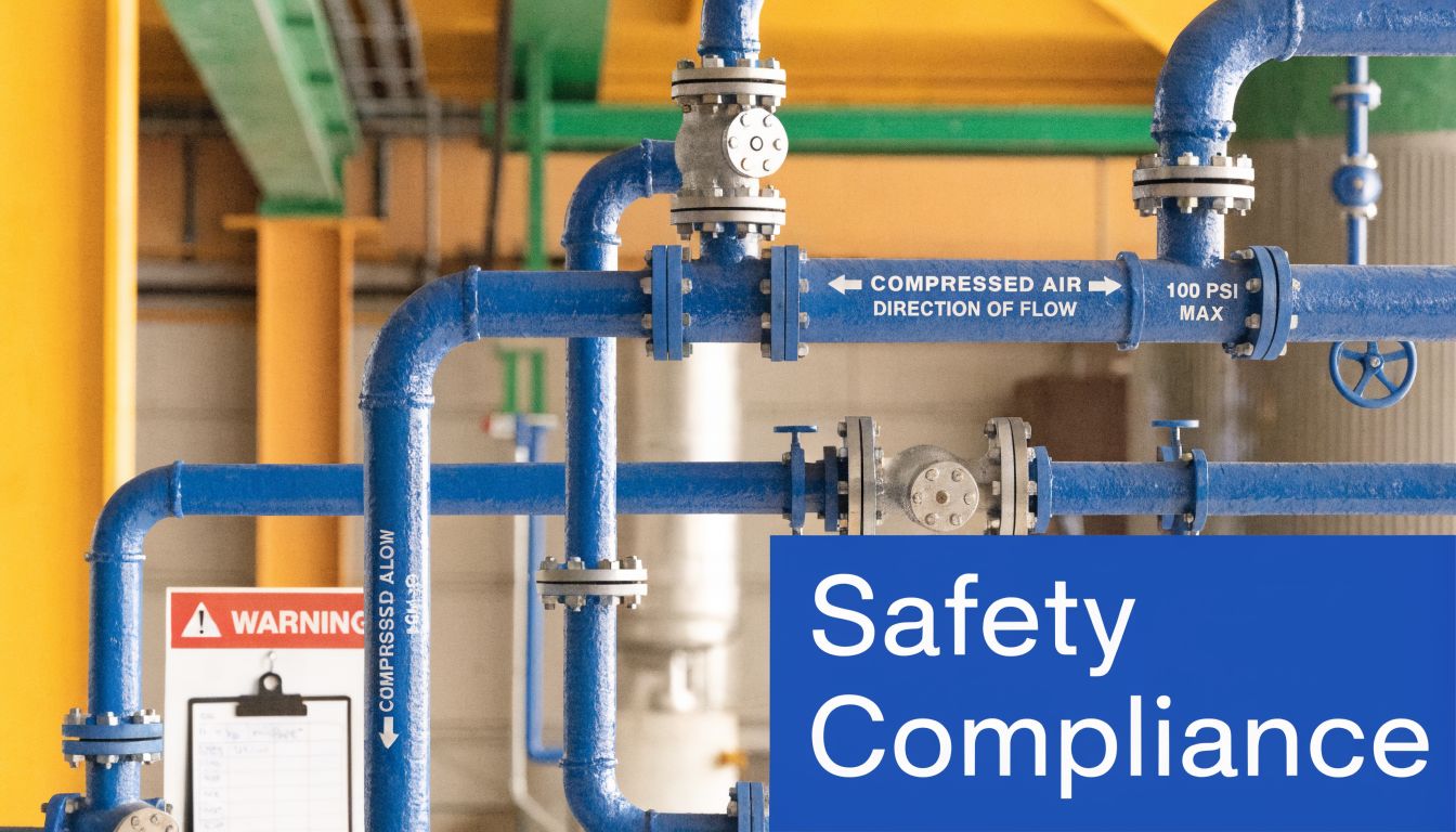
UK compliance thinking must remain practical. Under PSSR 2000, the pressure system has to be suitable for service, maintained, and examined where required. BCAS guidance also pushes engineers toward layouts and components that can be isolated, drained, inspected, and kept leak-free. If a component choice makes inspection awkward or encourages temporary repairs, it is the wrong choice, even if the purchase price looked attractive.
What works in mixed hydraulic applications
On hydraulic machinery and mobile power packs, compressed air often supports controls, purge functions, actuators, and ancillary devices. Those lines are easy to treat as secondary. That is a mistake.
Dirty or wet air causes sticking valves, erratic control behaviour, and nuisance faults that are hard to diagnose because the hydraulic side appears healthy. In mixed systems, specify the air side with the same discipline as the hydraulic side. Use clean materials, protect exposed runs, support against vibration, and make sure service items can be reached.
The best installations are usually the least dramatic. Clean bore pipe, sensible fittings, proper support, and components chosen for the actual UK operating environment keep the system running and make future changes far less painful.
Designing for Flow Pipe Sizing and Pressure Drop
A machine at the far end of the building keeps dropping out when two other lines come on. The usual reaction is to wind up the compressor pressure. That hides the fault for a while, raises running cost, and leaves the pipework problem in place.
Good pipe sizing starts with the pressure the end user needs, then works back through the network. In UK installations, a sensible design target is to keep distribution pressure drop low enough that controls, tools, and actuators still receive stable air under peak demand. BCAS guidance is useful here, but the practical point is simple. If the header is too small, velocity rises, friction rises with it, and the whole system becomes expensive to run.
Start with the furthest and most demanding point
Size from the worst-served point, not from the compressor connection.
That point is usually the longest run, the outlet with the highest short-term flow, or the machine that will not tolerate a sag in pressure. On hydraulic test rigs, mobile power packs, and factory control systems, that sensitivity matters. A few tenths of a bar lost through poor sizing can mean sticky pneumatic valves, weak actuation, or nuisance trips that look like electrical or hydraulic faults.
Use these inputs before choosing pipe size:
- Required pressure at point of use
- Peak flow through each section
- Equivalent length, including bends, tees, valves, and flexible connections
- Internal bore condition, because rough or reduced-bore fittings increase loss
- Realistic expansion allowance for future machines or service points
The practical sizing sequence
A methodical approach avoids oversights.
-
Set the minimum pressure the machine needs
Start with the pressure required during operation, not the nominal compressor discharge pressure. -
Assign demand to each branch properly
Do not size every leg as if the whole site flow passes through it. Main headers, sub-mains, and drops carry different duties. -
Keep header velocity under control
Fast air costs pressure. For many fixed industrial systems, mains are often kept around or below 6 m/s as a practical design guide. -
Reduce branch sizes with care
Branches can step down nearer the load, but aggressive reduction creates local losses that operators feel first at busy periods. -
Count every restriction in the line
Filters, regulators, quick couplers, hose tails, and small-bore isolation valves often cause more trouble than the straight pipe.
For anyone reviewing the calculations behind system pressure and load, this guide on how pressure is calculated in hydraulic and fluid systems gives useful background for sizing decisions.
Layout choices that protect pressure
Pipe size and pipe route have to work together.
A well-sized system can still perform poorly if the route is full of tight elbows, repeated reductions, and long detours around plant. I see this often on retrofit work where new machinery has been added one branch at a time. Each addition looked minor. The combined effect is a network that behaves well at low demand and falls over at shift change or during simultaneous tool use.
A few rules prevent that:
- Slope mains around 1:100 where drainage strategy requires it
- Use swept bends where space permits
- Take drops from the top or side of the main where appropriate
- Keep low points to a minimum and drain them properly
- Review older branches before adding more load to them
Raising the compressor setpoint is usually the most expensive way to deal with a pressure drop problem.
Why the ring main usually wins on larger sites
On larger industrial sites, a ring main gives better pressure stability than a dead-end layout because air can reach demand from two directions. That reduces the local pressure dip when one area suddenly draws hard. It also gives maintenance teams more options for isolating sections without shutting down half the building.
A straight main still has its place. In a small workshop, a compact bay, or a mobile assembly with short runs, it can be the right answer. The mistake is stretching that simple arrangement across a growing site without checking what the added demand does to velocity and pressure loss.
On mobile hydraulic equipment, the same principles apply in less forgiving spaces. Hose length, compact manifolds, small couplings, and tight packaging make every fitting matter more. That is why mobile air circuits should be sized on actual duty, not on whatever connection size happened to be available on the frame.
A useful visual walkthrough can help if you’re discussing sizing and restrictions with operators or apprentices:
The mistakes seen most often
These faults turn up repeatedly on site surveys and breakdown callouts:
| Mistake | What happens |
|---|---|
| Header matched too closely to compressor outlet size | Long runs suffer avoidable pressure loss |
| Too many sharp changes of direction | Friction increases and flow becomes less stable |
| Small fittings in an otherwise well-sized line | Local restrictions cancel out the benefit of larger pipe |
| Old branches reused without checking added demand | Pressure complaints appear only when several users draw air together |
| Compressor pressure increased to cover design errors | Power cost rises and the original fault remains |
For UK duty holders, this part of the design also ties back to suitability under PSSR 2000. If the system cannot deliver stable air at the equipment because of poor sizing, it is not a sound installation. Good flow design reduces wasted energy, prevents hard-to-trace production faults, and gives you a network that still works when the site is busy.
Installation and Compliance with UK Safety Law
A lot of compressed air problems start on the installation day, not six months later when production finally notices them.
A contractor hangs the main too far apart, leaves a branch under strain, skips a proper drain leg because there is a dryer on the package, and signs the job off. Then the compressor goes into regular duty, the pipe starts moving, joints begin to weep, and the site ends up paying for leaks, nuisance faults and a second round of work.
Support and bracing need to be designed into the job
Compressed air pipework has to be restrained properly, especially on systems with reciprocating compressors, long runs, flexible connections or mobile equipment exposed to vibration and shock. Support spacing is not something to guess on site. It should follow the pipe manufacturer’s data, the duty of the compressor, and the way the line is fixed to the structure.
In practice, good installation means supporting near changes in direction, keeping fittings free from side load, and allowing for thermal movement where pipe crosses warm plant rooms, external walls or exposed yard areas. UK sites see bigger temperature swings than many generic guides allow for, and that movement shows up at joints first.
Small fixings matter as well. On compact assemblies and smaller bore lines, properly selected supports such as 10 mm pipe clips help keep the line from rubbing, sagging or twisting under vibration.
Do not let the pipework carry the weight of valves, filters, hose reels or poor alignment from connected equipment.
UK compliance starts with identifying the pressure system properly
Compressed air is routine on British sites. The legal duties are still real.
For installations that fall within the Pressure Systems Safety Regulations 2000, the duty holder needs to know what sits inside the pressure boundary, what protection is in place, and what requires formal examination. That usually includes more than the compressor and receiver. Distribution pipework, isolation valves, filters and connected vessels can all matter depending on the arrangement.
BCAS good practice is useful here because it pushes teams to treat the network as a system, not just a compressor with some pipe attached. That matters in factories, but it also matters on mobile hydraulic equipment where compressed air supports controls, purging or auxiliary functions and may be added as an afterthought. Those hybrid installations are easy to get wrong because the air side often falls between mechanical, hydraulic and electrical scopes.
Where air quality affects downstream equipment, specify it clearly and test for it. Wet or dirty air can create faults that look like hydraulic problems at first. Slow pilot response, sticky actuators and intermittent valve behaviour often trace back to installation and air treatment, not to the hydraulic components that get blamed during breakdowns.
What a compliant installation looks like on site
The job should leave a system that can be isolated, inspected and maintained without guesswork.
That usually means:
- Clear isolation points for plant areas and major branches
- Accessible drains, filters and service items rather than fittings buried above ceilings or behind guarding
- Line identification and valve labelling so maintenance staff know what each section serves
- Documented pressure ratings for pipe, fittings, hoses and connected accessories
- A written scheme of examination where applicable, with equipment identified correctly
- Protection against impact and abrasion on mobile or exposed installations
Engineers who work across building services will recognise some of the routing discipline from an air conditioning pipe system, but compressed air adds stored-energy risk, pressure pulsation and different maintenance demands. The layout has to reflect that.
Commissioning is where installation quality shows itself
A proper handover includes leak testing, pressure checks at the points of use, drain operation checks, isolation valve checks and a visual inspection of support, alignment and joint condition. If the pipe moves when the compressor loads and unloads, the installation is not finished.
I would also check that any later extension can be isolated and tested without shutting down the whole site. That one decision saves a lot of production arguments.
Well-installed pipework costs less to own. It leaks less, passes inspection with fewer surprises, and gives maintenance teams a system they can work on safely under UK site conditions.
Condensate Management and Long-Term Maintenance
Every compressed air system makes water. The question is whether you control where it goes.
If you don’t, it ends up in the receiver, the mains, the drops, the tools, the control valves and, in winter, the coldest section of the installation. Once that starts, the symptoms spread. Corrosion inside the pipe, sticky valves, stained product, lazy cylinders and repeated drain problems all follow.
Keep water out of the main air path
Drying starts with system layout, but it doesn’t end there.
A correctly sloped main and proper drop design reduce how much condensate reaches the wrong places. After that, you need the right combination of receiver capacity, separation, dryer performance and drains.
The basics are straightforward:
- Drain receiver vessels regularly or fit reliable automatic drains
- Fit drains at low points and end points of the distribution network
- Use a dryer matched to the quality requirement of the process
- Inspect drains because an automatic drain that has failed shut is just a hidden reservoir
This matters even more when the air supply supports hydraulic control functions. Wet air and fine contamination are a poor combination around sensitive ancillary equipment.
Don’t ignore adjacent pipe disciplines
Engineers working across building and plant systems often benefit from comparing design habits between utilities. Looking at how another service handles routing, drainage and long-term access can sharpen your own decisions. Even something as different as an air conditioning pipe system is a reminder that fluid and gas distribution work best when fall, support, access and condensation control are treated as design fundamentals rather than afterthoughts.
A maintenance routine that actually helps
The sites that keep compressed air stable usually do simple things consistently.
A practical routine looks like this:
| Interval | Checks that matter |
|---|---|
| Daily | Check compressor status, receiver drains, obvious leaks, unusual water carryover |
| Weekly | Walk the main route, inspect supports, check drain operation, listen for fitting leaks |
| Monthly | Review filter condition, inspect regulators and isolation valves, verify pressure at key points |
| Planned shutdowns | Reassess branches added over time, inspect for corrosion, review whether demand has changed |
What maintenance teams should watch for
A few warning signs tell you the system is drifting away from good condition:
- Pressure complaints only during high activity
- Water appearing at one machine but not others
- Repeated regulator or valve issues on the same branch
- Hissing joints that everyone has learned to ignore
- Temporary hoses or ad-hoc additions becoming permanent
If a temporary compressed air fix is still there months later, it’s part of the system and should be engineered like it.
Long-term reliability comes from discipline, not novelty. Good compressor air piping stays reliable because someone keeps the drains working, the leaks under control, the supports sound and the documentation current.
If your air system is costing you time, energy or reliability, MA Hydraulics Ltd can help you assess the pipework, the layout and the practical fixes that will make a difference. Phone 01724 279508 today, or send us a message at https://www.mahydraulics.co.uk/contact-us/
