

You're on a quarry site during a night shift, multimeter in hand, trying to find out why a 24 V DC solenoid on a mobile hydraulic power pack won't pull in. The supply measures correctly at the panel, the fuse looks intact, and the machine worked on the previous shift. Yet the valve won't move, the relay chatters, or the coil runs hot enough to suggest a fault elsewhere.
That situation rarely comes down to one mysterious component. It usually reflects a basic design decision that wasn't checked properly, such as voltage drop in the wiring, an unsuitable relay contact, missing flyback suppression, poor earthing, or a component selected without considering its real operating environment. Circuit design basics become valuable when they help you prevent that fault, not merely explain it afterwards.
This practical guide connects electrical laws, components, schematics, design workflow and UK practice to the control electronics used around hydraulic power packs and industrial machinery. It also treats production readiness as part of the basics, because UK industry sources identify a continuing gap between theoretical semiconductor teaching and the practical skills needed for independent design work in the UK semiconductor sector.
Why Circuit Design Basics Matter on the Shop Floor
At 2 a.m., the maintenance engineer doesn't need a definition of resistance. They need to know whether the voltage measured at the coil is correct under load, whether the relay contact is dropping too much voltage, and whether the return path is connected to the intended 0 V rail. A schematic that omits terminal numbers or shows a diode the wrong way round makes that diagnosis slower and less certain.
Every control circuit around a hydraulic power pack has a job. A pressure switch may stop a motor starter, a proximity sensor may confirm cylinder position, and a relay may enable a CETOP directional valve only when an interlock is satisfied. The circuit designer has to make those decisions work repeatedly despite vibration, contamination, temperature changes, cable length, motor starting current and maintenance interventions.

A hydraulic circuit and its electrical controls should be considered together. The valve's function, pressure setting, flow requirement and emergency behaviour all affect the electrical choices around its coil. Engineers who are still building their wider system knowledge may find this practical guide to how hydraulics work useful alongside the electrical principles covered here.
The same logic applies outside hydraulics. A domestic alarm panel, for example, combines sensors, power supplies, relays, sounders and backup arrangements. A clear explanation of understanding home alarm systems shows why reliable operation depends on how individual circuit functions interact, rather than on any single component.
Shop-floor test: If a technician can't identify the supply, return, protection device, load and test points from your drawing, the design isn't finished.
The UK has a long history of circuit-design and semiconductor engineering. The first British-designed integrated circuit, Micronor 1, was produced under Government sponsorship in 1962 for Royal Navy computer use, while the Ferranti uncommitted logic array helped pioneer reusable gate-array architecture. The UK government has also stated that Britain holds a 40% share of Europe's electronics design industry and has 150 independent electronic system design houses, more than any other European country as recorded in this industry reference. Those milestones reinforce a useful point for today's engineer. Circuit design remains a practical engineering capability, not an academic side subject.
The Three Laws Every Circuit Designer Uses Daily
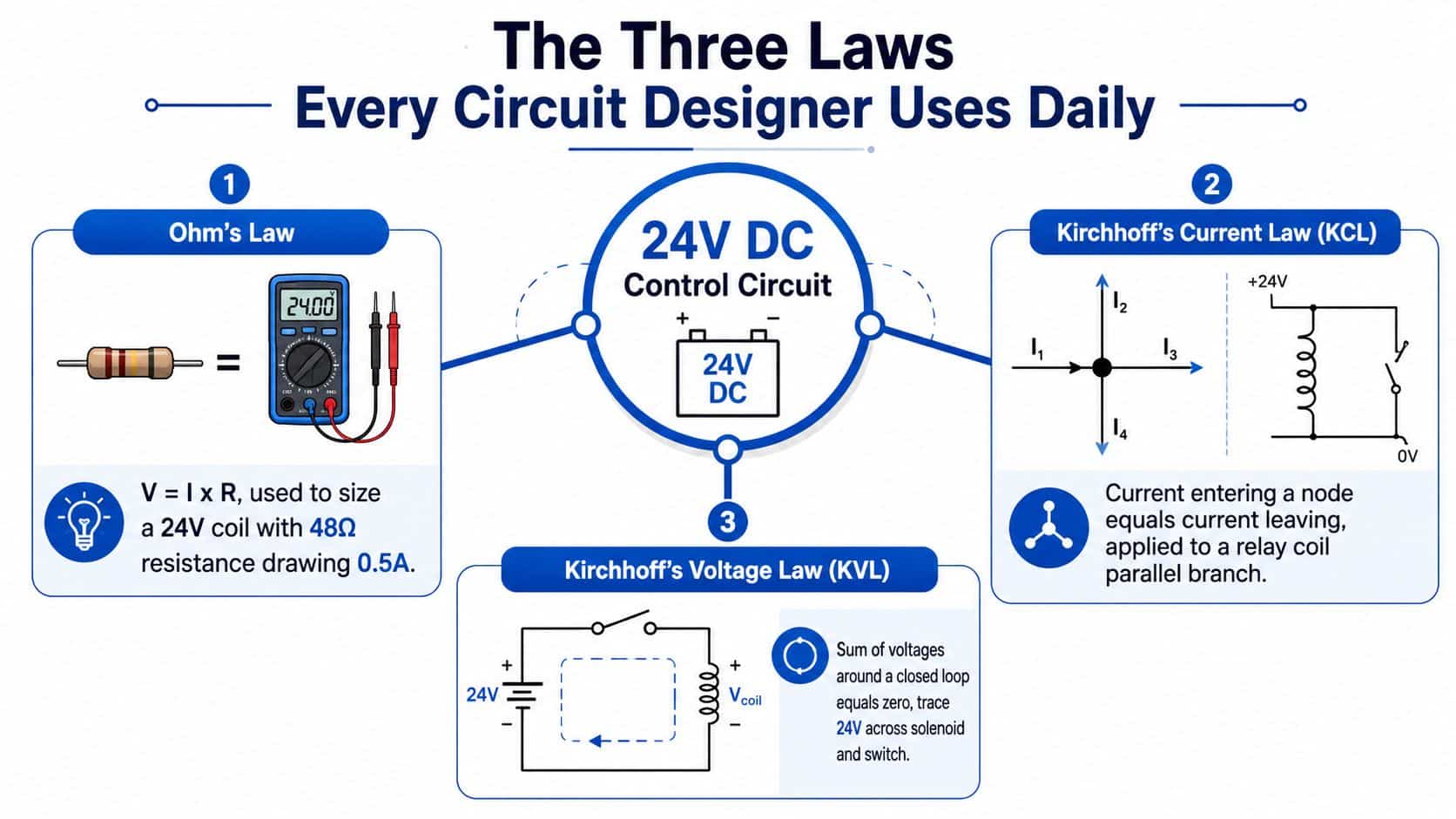
A 24 V DC control circuit can look simple: a power supply feeds a fuse, a relay contact and a CETOP solenoid coil. The three laws below let you check whether that circuit will work before you build it.
Ohm's law turns ratings into decisions
Ohm's law is V = I × R. Rearranged, current is voltage divided by resistance, and resistance is voltage divided by current. Suppose a 24 V coil has a resistance of 48 Ω. Its nominal current is:
I = V ÷ R = 24 V ÷ 48 Ω = 0.5 A
That calculation helps you assess the output device, fuse, wiring and power supply. It also shows why a coil's resistance alone isn't always enough. A cold coil, an AC coil and a pulse-operated solenoid can behave differently, so the manufacturer's current and duty information still matters.
Voltage drop uses the same relationship. If the wiring and contact resistance together total 0.4 Ω at 0.5 A, the drop is:
V = I × R = 0.5 A × 0.4 Ω = 0.2 V
That may be acceptable for a 24 V coil, but you should check the actual minimum operating voltage rather than relying on a rule of thumb. The calculation is the point. It tells you whether to increase conductor size, shorten the cable run or choose a different switching device.
KCL checks what happens at a junction
Kirchhoff's Current Law says that current entering a node equals current leaving it. If a 24 V supply feeds a junction with a relay-coil branch drawing 0.5 A and an indicator branch drawing 0.02 A, the incoming current must be 0.52 A.
This matters when several loads share a control rail. The supply, fuse and common return must handle the combined demand, not just the current of the largest individual device. KCL also exposes incorrect assumptions in parallel circuits. If your measured current is much higher than the sum of the expected branches, look for a short, an incorrectly wired load or an unexpected current path.
KVL verifies the complete loop
Kirchhoff's Voltage Law says that the algebraic sum of voltages around a closed loop is zero. In practical terms, the supply voltage must equal the voltage drops across the fuse, relay contact, wiring and coil.
For the example circuit, if the coil needs 23.7 V while the wiring loses 0.2 V and the contact loses 0.1 V, the remaining drop is only 0 V across an ideal fuse. A real circuit still has tolerances, so measure under operating conditions and include the power supply's minimum output in the design review. These checks support decisions about wire sizing, fuse selection and contactor or relay suitability.
For engineers connecting electrical behaviour to hydraulic performance, how pressure is calculated provides useful context. Pressure, flow and electrical control current describe different parts of the same machine, and a reliable design keeps those relationships visible.
Components You Will Meet in Hydraulic and Industrial Control Circuits
Component selection becomes easier when you begin with the job each part must perform. A resistor that looks insignificant on a drawing may provide current sensing, a pull-down path or protection for a digital input. A capacitor may smooth a DC link or suppress noise created when a solenoid switches.
Passive components and suppression parts
- Resistors: Set input thresholds, provide pull-up or pull-down bias, or create a measurable voltage across a current-sensing path.
- Capacitors: Smooth rectified DC in a power supply and suppress high-frequency noise near relay or solenoid wiring.
- Inductors: Reduce conducted interference in a supply or form the magnetic element of a relay or solenoid coil.
- Flyback diodes: Provide a controlled path for inductive current when a DC coil is switched off. Connect the diode with the correct polarity, otherwise it can short the supply when the coil is energised.
- TVS devices: Clamp fast voltage transients on a 24 V rail or across a coil where switching speed and protection need balancing.
- Zener diodes: Limit voltage at a defined level and can protect a transistor driver from a coil transient.
- MOVs: Absorb transient energy, commonly on AC switching circuits, but they must be selected for the system voltage and expected surge conditions.
The choice between a simple diode, a TVS device or a more complex suppression network isn't cosmetic. A diode can lengthen relay release time, which may affect a valve sequence or an interlock. Check the valve manufacturer's instructions and the required response before choosing suppression.
Active switching and signal parts
Relays and contactors switch loads that a PLC output may not handle directly. A relay might operate a solenoid, while a contactor controls a motor starter. Fuses and miniature circuit breakers protect conductors and equipment against faults, but they don't replace correct overload protection or safe isolation.
Rectifier diodes and bridge rectifiers convert AC into DC in power supplies. Transistors and MOSFETs provide efficient low-side or high-side driver stages for proportional valves, pump clutches or auxiliary actuators. Op-amps and comparators condition pressure-transducer signals, create thresholds and provide simple fault detection. A 555 timer or a logic gate can still be useful for a delay, pulse function or basic interlock in a small standalone circuit, although a PLC or dedicated controller may be more appropriate for a complex machine.
| Component | Typical Function in Hydraulic/Industrial Control |
|---|---|
| Resistor | Current sensing, input bias or signal scaling |
| Capacitor | Supply smoothing and coil-noise suppression |
| Relay | Isolation and switching for solenoids or auxiliary loads |
| Contactor | Switching a hydraulic pump motor starter |
| Fuse or MCB | Protection of conductors and control equipment |
| MOSFET | Efficient electronic drive for a proportional valve |
| Comparator | Pressure or position threshold detection |
| Bridge rectifier | Conversion of AC input to a DC control supply |
| TVS diode | Transient clamping on a switching rail |
The electrical choice should match the hydraulic function. If you're comparing types of hydraulic valves, note whether the valve is on-off, proportional, load-holding or sequence-related. That classification affects the required driver, feedback, suppression and fault response.
Reading and Drawing Schematics That Other Engineers Can Follow
A schematic is a shared engineering language. It should show how the circuit works electrically and give a maintenance engineer enough information to locate the corresponding physical parts.
Trace a CETOP coil circuit logically
Start with the 24 V DC supply. Mark the positive rail as +24 V and the return as 0 V. Place the fuse where it protects the intended part of the circuit, then show the relay contact, terminal strip connections and solenoid coil in the order that the current path follows.
For a directional valve, label the coils as Y1 and Y2, or use the project's established reference designators. Draw a flyback diode across each DC coil, with the cathode connected towards +24 V and the anode towards the switching side. If the drawing shows the diode reversed, the circuit may create a direct short when the supply is applied.
The terminal numbers should match the physical strip. A technician shouldn't have to infer that terminal 14 on the drawing becomes terminal 27 in the cabinet. Include wire numbers, connector references and cross-references when the circuit continues on another sheet.

Make relay logic readable
A start-stop circuit normally uses a normally open start push button, a normally closed stop push button, an overload contact, a contactor coil and a normally open auxiliary contact for the latch or seal-in path. The engineer should be able to follow the energisation path from the supply rail through the closed permissive contacts to the coil.
Use consistent reference designators and distinguish normally open from normally closed contacts clearly. A title block should identify the machine, drawing number, sheet number, revision and approval status. The revision history must explain what changed, especially when terminal assignments or safety functions have been altered.
Drawing rule: Show the circuit in a way that lets someone test it from left to right, then match every electrical point to the cabinet and machine.
A serviceable drawing also needs polarity markers on DC rails, a legend for unusual symbols and line weights that remain legible when printed. A wiring diagram can support the same disciplined fault tracing used when repairing a logic board. This practical resource on Steel City IT logic board repair offers useful context for following tracks, test points and component relationships, even though the applications differ.
A Practical Design Workflow from Specification to Prototype
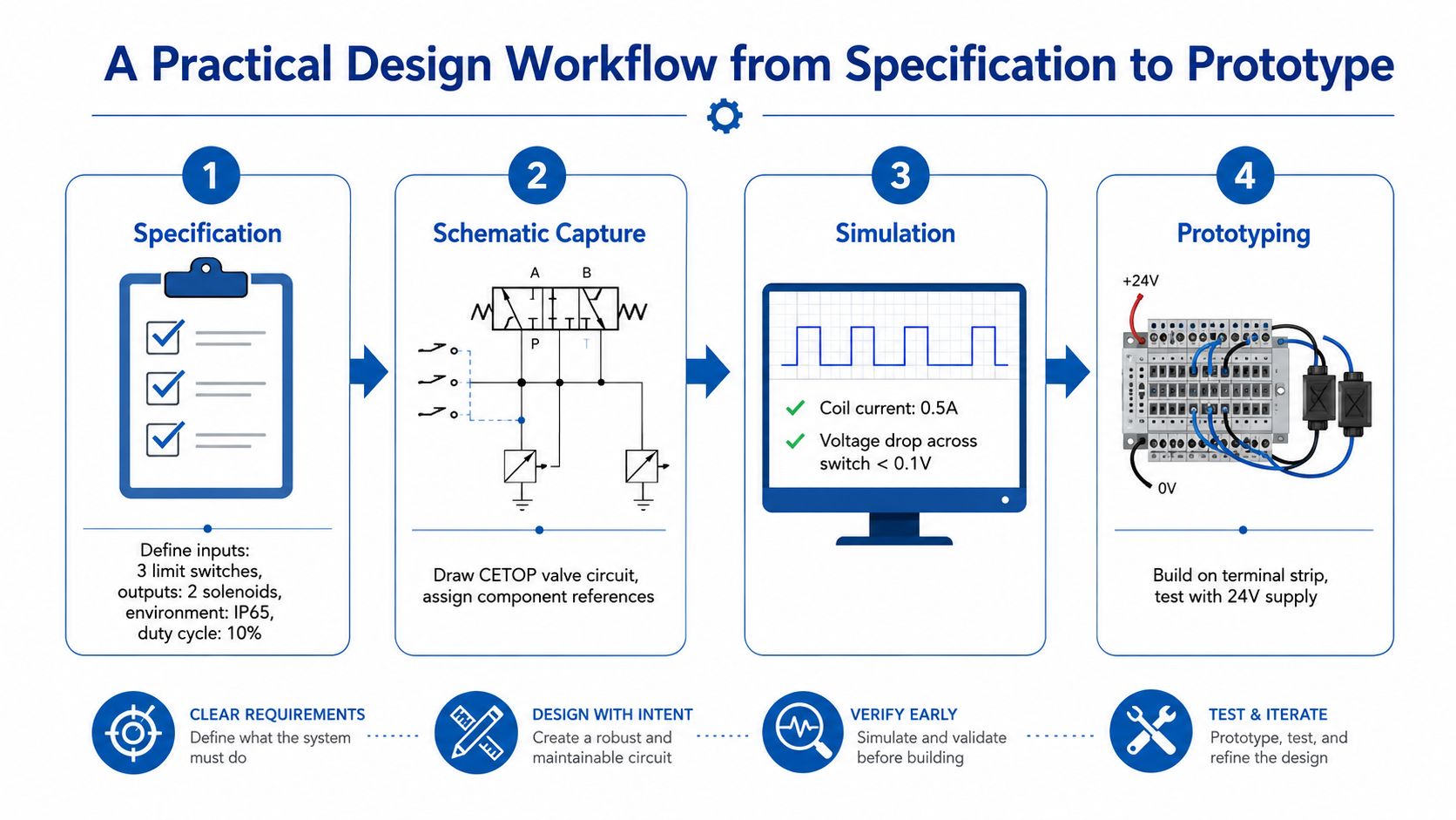
Production-ready circuit design starts before the first symbol is placed. Write a short functional specification that defines the inputs, outputs, supply voltage, operating environment, duty cycle, fault behaviour and relevant standards. For a hydraulic power pack, that may include pressure switches, temperature feedback, motor control, directional valve coils, emergency stop behaviour and the conditions that prevent a pump from starting.
Define, select and document
Choose components against their operating conditions, not just their nominal ratings. Capacitors should have voltage headroom, and a practical internal design rule may be to operate them at no more than 80% of their voltage rating. Contactors need to suit inductive loads and motor starting conditions, while semiconductors require a thermal check against the worst-case ambient temperature and enclosure conditions.
Build the bill of materials alongside the schematic. Record the manufacturer, part number, approved alternatives, package or mounting style, electrical rating, temperature range and availability status. This matters when a relay or contactor becomes difficult to source. A substitute must match the electrical function, mechanical fit, terminal arrangement and approval requirements.
The UK Semiconductor Sector Study 2026 describes continuing barriers involving talent availability, scale-up capital and UK operating costs, including energy, while also highlighting strategic interest in chip design and opportunities involving silicon carbide, gallium nitride and photonics in its sector assessment. For control engineers, that wider context reinforces the need to check efficiency, thermal headroom and parts availability early.
Simulate and test deliberately
A quick SPICE model or vendor simulation can expose an incorrect resistor value, an unexpected current path or an unsuitable switching transient before metal is cut. It won't replace a physical test, but it can make the bench test more focused. For a valve circuit, verify coil current, switching behaviour, voltage drop and the response of the suppression device.
Build the prototype on a labelled terminal strip or suitable test fixture. Test in a controlled sequence:
- No-load check: Confirm polarity, continuity, insulation and supply behaviour.
- Functional check: Operate each input, relay, contactor and valve output separately.
- Full-load check: Measure current, voltage at the load and temperature at relevant components.
- Fault check: Test fuse operation, overload response, open-circuit inputs and loss of supply.
- EMC pre-check: Look for false switching, sensor disturbance and noise during motor or valve operation.
Finish with a design review gate. Sign off safety functions, component ratings, thermal assumptions, documentation, standards evidence and the test record before production. This workflow turns circuit design basics into a repeatable engineering method.
Common Pitfalls and How to Catch Them Early
Most control-panel faults are predictable. The useful response isn't a longer warning list. It's assigning each risk to the stage where the team can still change the design cheaply.
Find the failure before commissioning
Earth loops can appear when the cabinet, machine chassis and signal reference have multiple unintended paths. Define the earthing and reference strategy during specification, then verify it during design review and commissioning.
Undersized contactors may chatter or fail when motor inrush exceeds what the selected device can tolerate. Check the load category and starting condition during the derating review, not after the first start attempt.
Unaccounted solenoid inrush can weld relay contacts or trip a control supply. Use the manufacturer's energisation and holding data in component selection, then confirm the measured current during prototype testing.
Missing or incorrectly rated fusing leaves the 24 V rail or its branches poorly protected. Select protection after calculating expected branch demand and conductor capacity, then test the fault response under controlled conditions.
Absent flyback protection exposes relay contacts, PLC outputs and transistor stages to switching transients. Check every inductive DC load on the schematic and verify diode or TVS polarity before applying power.
Cable segregation errors can couple motor and valve noise into analogue or sensor wiring. Address segregation during enclosure and harness layout, then include noise checks in the commissioning script.
Inadequate enclosure protection allows water, dust or cleaning fluids to reach the electronics. Set the environmental and ingress requirements in the specification, and inspect the finished installation rather than trusting the drawing alone.
Documentation drift leaves the as-built panel different from the approved schematic. Make red-line changes part of commissioning and issue the revised drawing before handover.
For a separate explanation of breaker wiring principles, how to wire a 15 amp breaker can help clarify the relationship between protective devices and conductors. Apply the same disciplined thinking to the machine's control and power circuits, while following the applicable UK requirements and safe-isolation procedures.
UK Standards, Safety and Real-World Design Constraints
UK practice should influence design decisions from the first specification, not appear as a compliance note at the end. The organisation that became the British Standards Institution began as the Engineering Standards Committee in 1901, and the UK government formally recognised BSI as the only organisation for issuing standards in Britain in 1942. The BS 1363 plug-and-socket system was introduced in the UK in 1947 after debate that began in June 1942, illustrating how standardisation shapes practical assumptions about safe and interoperable electrical connections in this history of BSI.
For machine panels, engineers commonly need to consider BS 7671 for electrical installation practices, BS EN ISO 13849-1 for safety-related control functions, and the evidence needed for UKCA or CE marking where applicable. The exact route depends on the machine, market and declared conformity requirements, so the responsible designer should confirm the current standards and assessment obligations.
Energy consumption, component availability and service conditions also affect reliability. A low standby draw can matter where equipment operates for long periods, while thermal performance becomes more difficult inside a compact enclosure or mobile machine. Copper, relays and contactors may also require substitution planning, so the bill of materials should identify acceptable alternatives rather than relying on one unavailable part.
| Design aspect | To specification only | To specification plus UK reality |
|---|---|---|
| Component choice | Meets nominal electrical ratings | Includes derating, thermal margin and approved alternatives |
| Wiring | Carries expected load | Supports installation method, service access and UK practice |
| Safety | Lists required functions | Verifies fault behaviour, documentation and conformity evidence |
| Energy | Operates the circuit | Reviews standby draw, heat and operating cost |
| Procurement | Names a preferred part | Plans substitutions without changing the intended function |
A panel designed only on paper may pass its initial test yet frustrate the person maintaining it. A panel designed to the specification and its operating environment is more likely to remain diagnosable, serviceable and reliable.
UK public-sector style guidance recommends using metric units, writing measurements out at first mention with the abbreviation in brackets, and separating the abbreviation from the number with a space in the ONS measurement guidance. GOV.UK guidance also recommends numerals, Celsius for temperature and ranges written with “to” rather than a hyphen in its style guide. Those details improve consistency in drawings, specifications and maintenance records.
Next Steps, Resources and How MA Hydraulics Can Help
Keep a personal library of proven schematics, fault records, datasheets and design-review checklists. Study BS 7671 through the IET, obtain standards from BSI, and use the IET Code of Practice for low-voltage electrical installations where it applies. Manufacturer datasheets from suppliers such as RS Components and Farnell are valuable for checking coil current, contact ratings, suppression requirements, operating temperature and approved alternatives.
Reverse-engineering an existing hydraulic power-pack panel is a practical exercise. Trace the supply and return rails, identify every protection device, compare the drawing with the wiring, and note how the designer handled interlocks, test access and component labels. Joining the IET or a regional engineering society can add useful peer discussion to that hands-on learning.
For engineers specifying hydraulic control systems, MA Hydraulics Ltd can provide application support, panel-build guidance and component-selection assistance for mobile and industrial machinery operating in the UK. The team also assembles Hydronit mini power packs, builds bespoke industrial power packs up to 11 kW, and supports component selection, cross-references and complete hydraulic assemblies.
Government accessibility guidance recommends embedding videos with an iframe whose title includes the video title and “(video)”, leaving line spaces around the embed, and providing transcripts and closed captions for accessible video content. Check embedded video frames for incorrect sizing before publishing, and verify that surrounding content remains visible using the GOV.UK video guidance.
If you're specifying a hydraulic power pack or troubleshooting a control circuit, contact MA Hydraulics Ltd for practical help with component selection, circuit requirements and bespoke power solutions. Visit MA Hydraulics Ltd, phone 01724 279508 today, or send us a message with your application details.
