
A suction hose always gets blamed after the pump starts sounding rough, but the hose is usually the first place to look when a plant room loses prime, a tractor slows down on a cold morning, or a transfer set suddenly starts groaning. On the vacuum side, small mistakes turn into big losses fast, because the pump can only work properly if the inlet stays fed, sealed and unruly-free. In practice, that means the hose is not just a connector, it's part of the pump's survival system.
What a Suction Hose Does in a System
A suction hose sits on the vacuum side of a pump circuit, where the pump is drawing fluid from a tank, sump, tote or open source into the inlet. That is different from a discharge hose, which carries fluid after the pump has already raised the pressure. Get the suction side wrong and the whole system becomes noisy, erratic and difficult to prime.
The job is simple, but the conditions are not
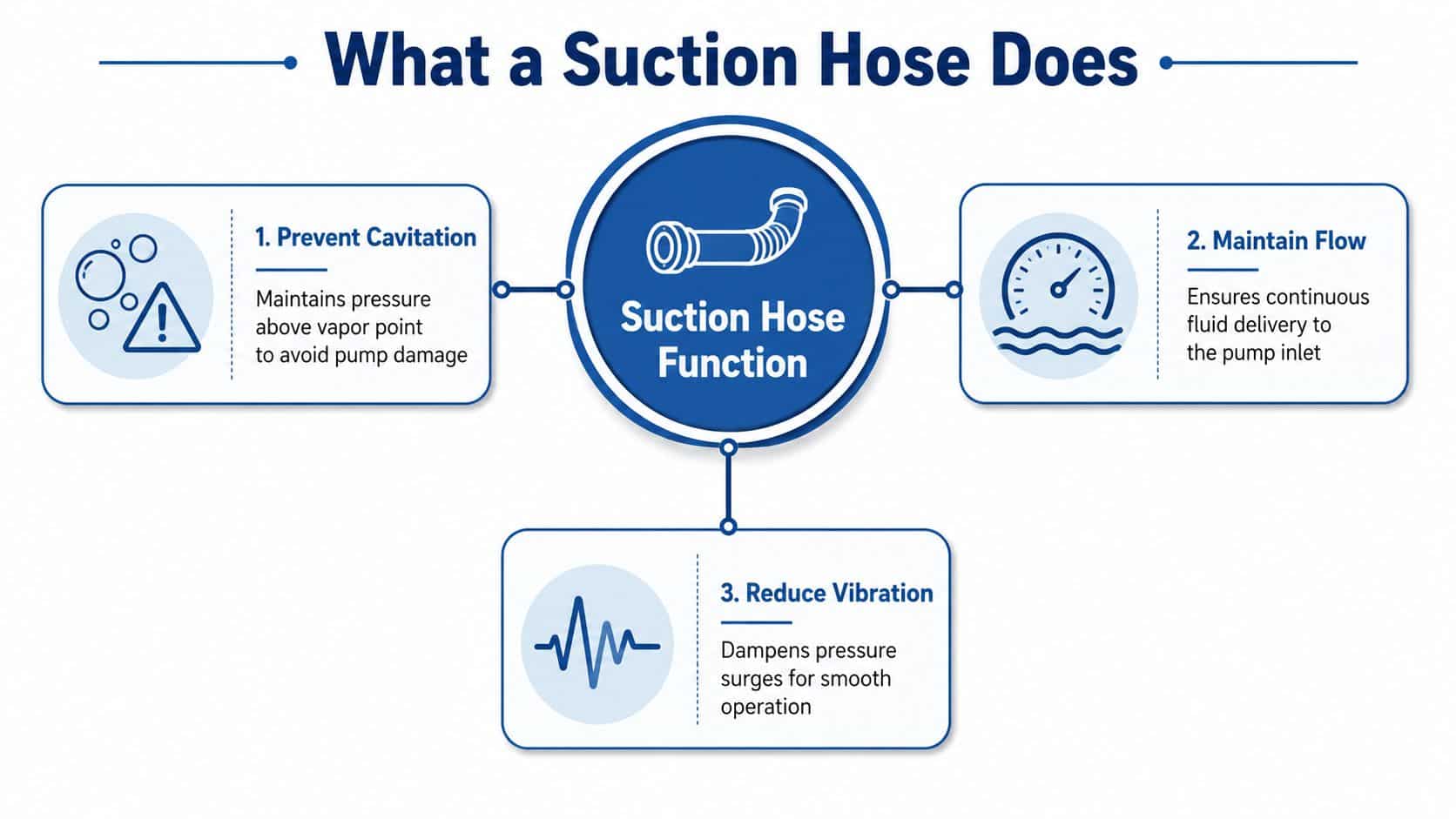
The hose has to keep a continuous fluid path available while the pump creates low pressure at the inlet. That sounds straightforward until you factor in hose length, bend radius, air leaks, vibration, and the fact that suction lines can collapse if the construction is too light for the duty. A suction hose that looks fine on the outside can still be the reason a pump is cavitating or starving.
Practical rule: if the pump inlet is struggling, treat the suction line as the first suspect, not the last.
The suction hose functions as the link that lets atmosphere do the pushing while the pump manages the pressure difference. That is why inlet conditions matter so much. If the line leaks air, kinks, flattens or runs too long, the pump pays for it immediately in heat, noise and lost performance.
The same logic shows up in other vacuum systems too. A useful overview of central vacuum layout, routing and hose behaviour is the Can Do Duct Cleaning home cleaning advice article, which reinforces how strongly suction performance depends on clean routing and leak control.
For the broader hydraulic context, it helps to review how hydraulics work before treating the hose as a standalone part. The pump, inlet line and fluid source all interact, and the suction hose only makes sense once you look at that circuit as a whole.
A Short History of Suction Hose Design
The modern suction hose has a much older engineering story than many realise. In the UK, the historical root runs back to firefighting, where John Lofting, born Jan Loftingh, is credited with introducing a wire-reinforced suction or draft hose around 1690, building on Dutch hose developments from about 1675. That early design solved a very practical problem, moving water from unpressurised sources into pumps, and it set a pattern that still shapes hose design today. The historical record also shows how long old ideas can stay useful, since riveted leather hose was still in use in some fire departments as late as 1900 FFAM development of fire hose.
Why the old design choices still matter
Each generation of hose solved a different weakness. Leather and riveted assemblies brought the first workable suction lines, but they were heavy and had obvious durability limits. Later rubber-lined and woven constructions improved flexibility and handling, then reinforced plastics and elastomers brought more consistent bores, better chemical compatibility and easier routing in confined plant spaces.
What hasn't changed is the basic engineering requirement. A suction hose still has to resist collapse under vacuum, keep its shape through bends, and move fluid with the least possible inlet loss. That's why helical wire reinforcement, kink resistance and realistic bend limits still matter just as much in modern plant rooms as they did in early fire appliances.
A design line that never really disappeared
Modern suction hose materials may be different, but the design logic is recognisable. Heavier-duty pumping still needs a hose that keeps its bore open, and mobile equipment still needs something that can be routed without tearing itself apart on the first tight turn. That continuity is useful, because it reminds engineers that a “new” hose isn't automatically a better hose if the reinforcement and bend performance aren't right for the job.
The same old trade-off also explains why suction hose selection has always been about compromise. Stronger reinforcement improves vacuum behaviour, but it can add stiffness. Lighter materials make handling easier, but they can lose stability if the run is badly supported. The best designs balance both, rather than chasing one property at the expense of the rest.
Construction Layers and Common Materials
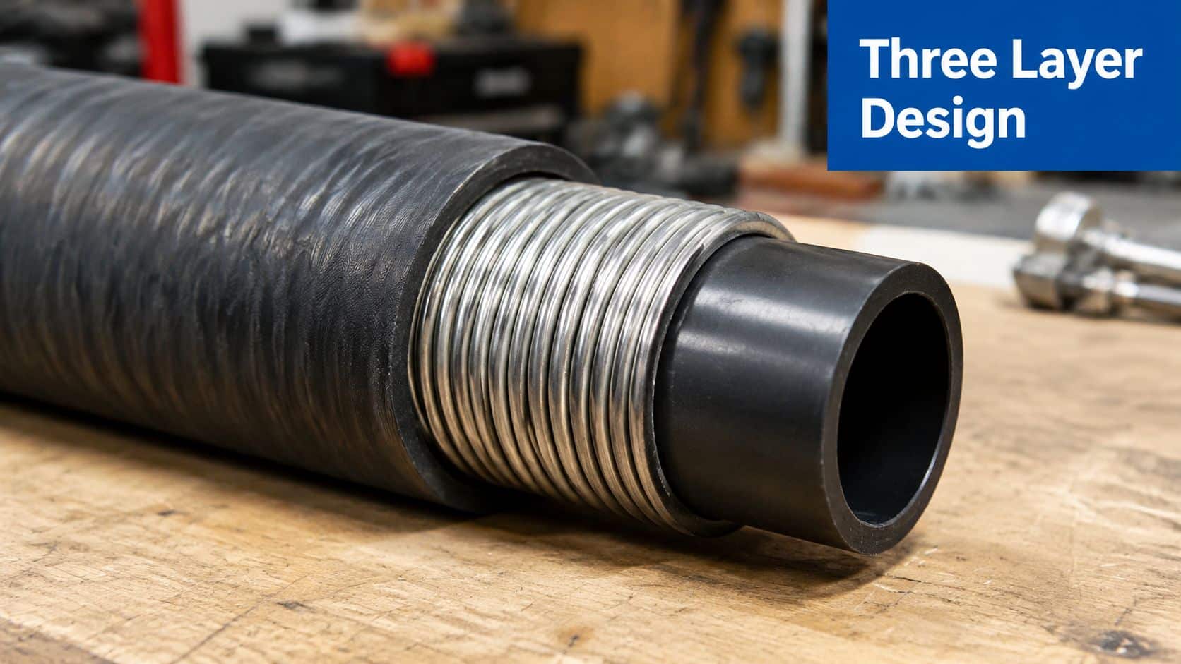
A suction hose only behaves properly when all three layers do their jobs together. The inner tube carries the fluid, the reinforcement keeps the bore open under vacuum, and the outer cover protects the assembly from weather, handling damage and site contamination. If any one of those layers is wrong for the duty, the hose may still look serviceable while failing on suction.
What each layer is really doing
The inner tube matters more than many buyers expect, because it has to suit the fluid as well as the temperature. A smooth bore helps reduce resistance, while the reinforcement, often a helical wire, steel wire, textile braid or embedded helix, gives the hose its resistance to flattening. The outer cover is the visible part everyone notices, but it's only one part of the system.
A hose that feels tough in the hand can still be a poor suction hose if the reinforcement is wrong for the vacuum duty.
Material choice follows the fluid and the environment. PVC suction hose is common for lighter agricultural and water-transfer tasks. NBR is usually chosen where petroleum-based hydraulic fluid and oils are involved, EPDM suits hot water, glycol and many chemical duties, and polyurethane is often picked where abrasion from solids is the main concern. The right answer depends on what's being moved, at what temperature, and through what kind of routing.
Bore size is part of the construction decision
UK practice commonly refers to suction hose sizes in standard metric nominal diameters of 7, 9, 12.5 and 15 cm suction hose sizing overview. In some layouts, the two smallest sizes are paired as twin lines when a single larger bore won't fit. That isn't a neat theoretical preference, it's a practical way of keeping flow usable when packaging space or routing makes a larger single hose unrealistic.
The important point is that construction and size can't be separated. You don't pick the material first, then worry about the bore later. You match the fluid, the route, the bend radius and the suction duty together, because that's what keeps the hose stable once the pump starts working.
Sizing Suction Hose for Hydraulic and Pump Systems
A suction line that looks fine on paper can still ruin a pump once it is fitted. If the bore is too small, the pump has to work harder to draw fluid, inlet losses climb quickly with length, and the hose can start to behave like a restriction rather than a feed line. On plant rooms, tractors and OEM builds, I have seen that show up as noisy running, weak prime and cavitation long before anyone thinks to check the suction side.
A sizing rule that actually helps on site
A practical guide for suction lines says the line should be increased by about 1 cm per metre of suction line and kept short and straight, with abrupt cross-section changes avoided Hawe suction line engineering guide. The same guide also makes the point that suction lines should be at least as large as the inlet, and that elbows and air leaks are common causes of poor performance.
The worked sizing example in the guide is useful because it shows how line length changes the answer. It calls for a 22 mm line for lengths of 3 to 6 m, and a 28 mm line for 10 to 12 m runs. That is the sort of simple rule that helps when space is tight and you are trying to keep a pump fed without forcing the hose into a bad route.
A larger bore is not a free pass. It can reduce inlet loss, but it also takes more room, needs a gentler route and is easier to misinstall if the bend radius is tight.
A straightforward four-step method
- Measure the required flow. If you do not know what the pump must move, the rest is guesswork.
- Choose the minimum bore from velocity and inlet size. Keep the inlet side calm rather than making the pump drag through a restriction.
- Add length allowance. Use the 1 cm per metre rule as a practical starting point.
- Check bend radius and routing. If the hose cannot be installed without flattening or stress, the size choice is not finished.
Useful habit: size the hose for the route you can actually build, not the route you wish you had.
The reason this matters is straightforward. A suction hose does not fail only because it is too small in a brochure sense. It fails when the route, fittings and bend geometry turn a decent component into a restrictive intake, or when a small air leak on the suction side lets the pump pull froth instead of fluid. That is why experienced engineers spend more time on suction than discharge when they are chasing a pump complaint.
Video demonstration for installers and apprentices:
Pressure, Vacuum and Bend Radius Ratings Compared
The mistake I see most often is someone reading the highest vacuum figure in a catalogue and assuming the hose is automatically suitable. It isn't that simple. Vacuum rating, working pressure and bend radius move together, and the wrong balance can make a hose unusable even when the headline vacuum number looks healthy.
Reading a typical specification table properly
One published PVC suction hose series is rated at 29 in/Hg vacuum across multiple sizes, but the working pressure falls from 88 psi at 1 in I.D. to 30 psi at 8 in I.D., while minimum bend radius grows from 3 in to 20 in Austin Hose suction hose specification. That's the lesson. A larger hose can reduce loss and improve suction behaviour, but it also becomes less forgiving to route.
| Typical Suction Hose Rating Behaviour by Internal Diameter | |||
|---|---|---|---|
| Nominal I.D. | Vacuum Rating | Working Pressure | Min. Bend Radius |
| 1 in | 29 in/Hg | 88 psi | 3 in |
| 8 in | 29 in/Hg | 30 psi | 20 in |
The takeaway for UK engineers is practical. The number to watch is rarely the vacuum rating alone. It's whether the hose can be installed with a realistic bend radius, without flattening under suction, and whether the planned duty sits inside the working pressure envelope for that size.
A stricter performance benchmark
Fire-service draft hose testing gives a much harsher view of what “good enough” means. In a USDA study, all suction hose tested held a vacuum of 25 in of mercury without collapse or other failure, and all draft hose withstood at least 200 psig hydrostatic proof pressure with no leaks, cracks, breaks, permanent deformation, mechanical damage or structural failure USDA draft-hose study. That's a useful benchmark because it shows suction hose is tested against measurable structural limits, not just a vague promise of being vacuum-resistant.
The matching construction study also records standardised hose geometry, including nominal diameters, hose weights for 8 ft and 10 ft lengths, minimum bend radius and proof pressure values USDA draft-hose measurements. For a working engineer, that reinforces the point that selection is about geometry and handling limits as much as it is about material.
Installation Best Practices for UK Plant Rooms and Mobile Builds
A suction hose can look fine on the bench and still cause trouble as soon as the pump starts drawing. The usual signs are rough running, inlet noise, loss of prime, or a hose that goes slightly oval every time the circuit loads up. In UK plant rooms and mobile retrofits, the answer is usually better routing and support, not a dearer hose.
The layout rules that matter
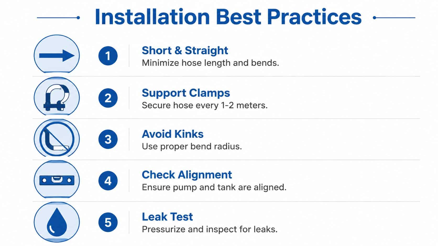
Keep the suction line as short and straight as possible. Match the bore to the inlet size, avoid elbows and sudden changes in section, and keep every joint tight enough to prevent air ingress. The suction side should behave like a direct run, not a route filled with unnecessary turns.
The hose end in the tank should sit above the bottom and below the fluid level, so it does not pull sludge off the floor or draw air from the surface. The run also needs proper support so it does not sag under vacuum, because sagging creates local flattening and extra loss. Where the route is tight, a correctly chosen flexible section with the right bend radius is a better answer than a forced bend that spends its life trying to spring back.
For repeatable workshop standards, follow the practical points set out in MA Hydraulics installation guidance. That gives installers a clearer basis for layout checks, leak testing and fitment discipline before a machine goes into service.
What works on mobile and agricultural builds
Tight packaging is where suction problems often start. A pair of 45-degree fittings is usually kinder to the line than a hard 90-degree bend, and longer runs should be given anti-collapse reinforcement if the hose is expected to hold shape under suction. That matters on tractors, sprayers and compact OEM builds, where vibration and heat creep in together and the line sees constant movement.
Practical rule: if you cannot route the suction line cleanly, change the layout before you change the pump.
On mobile kit, I also look at service access. If the hose cannot be inspected without stripping half the bay, it will not be checked often enough. That is where a clean installation pays off, because the operator gets fewer inlet faults, the pump keeps prime more reliably, and cavitation noise stays out of the cab or plant room. The An infographic titled Installation Best Practices showing five steps for installing suction hoses with accompanying icons. also gives a quick visual check on the same fitting sequence.
A good installation is judged at rest and under load. Build the suction side so it stays open, stays sealed and stays supported, then prove it before the machine leaves the bay.
Common Failure Modes and How to Diagnose Them
A suction hose usually gives warning signs before it gives up. The first clues are often a harsher pump note, inlet chatter, hesitation on startup or a line that looks fine until the system is under suction and moving oil. Read those symptoms properly and you save time, because the wrong diagnosis sends you chasing the wrong side of the circuit.
Symptom to cause mapping
Harsh pump noise and inlet chatter point first to air ingress or a suction-side restriction. In practice, that is usually where I start on plant rooms, tractors and OEM builds, because the pump is reacting to poor inlet conditions rather than a discharge fault. If the hose is flattening, holding an oval shape or recovering badly after depressurisation, internal collapse or weak reinforcement is the more likely issue. If the cover is cut or abraded, the hose may still run for a period, but the failure path has already opened up.
Chemical attack is easier to miss because the outside can still look respectable while the bore is changing. A wrong hose compound can let the inner tube swell, soften or break down, especially when the fluid and elastomer are badly matched. Fatigue cracking tends to show up at bend points, coupling terminations and anywhere the line is being held at an awkward angle for too long.
A good reminder of what hidden contamination and internal deterioration can do comes from dental suction systems. A peer-reviewed study found P. aeruginosa in 22.6% of samples on the first working day and 18.3% on the last working day, with total viable counts of 235 × 10^3 cfu/mL and 232 × 10^3 cfu/mL respectively dental-unit suction hose study. The same study reported that all samples were contaminated with viable bacteria and that about 68.0% were heavily contaminated above 300 cfu/mL. As noted in the same dental-unit suction hose study, a suction line can become a reservoir as well as a conduit.
Cavitation is often a system problem
Cavitation gets blamed on the pump because that is where the noise shows up, but suction-side conditions usually set it off. If the line is too long, poorly supported, leaking air or undersized, the pump inlet runs short of fluid and starts pulling vapour and bubbles instead. The fix is usually to respec the hose, reroute the line or remove the air leak, not to swap the pump and hope. The same kind of failure logic is discussed in hydraulic hose failure causes, where repeated stress and poor layout shorten service life.
For a wider comparison outside hydraulics, the discussion around cloth versus metal dryer vent safety is a useful reminder that flexible ducting and hose assemblies can fail for reasons that are not obvious from the outside. The same principle applies here, a flexible line can look intact while still being unsafe for the duty.
Maintenance, Inspection and When to Replace
A suction hose should be treated as a condition-based item, not a fit-and-forget part. Weekly checks are sensible on hard-used lines, and it's worth remembering that keeping bends gentle matters just as much as checking for visible wear. If a line is being forced round a bend greater than 90°, it's already living too hard for long life.
What to inspect
Look for cover abrasion, exposed reinforcement, blistering, persistent flattening after depressurisation and any sign of coupling slippage. Check the joints for air ingress symptoms too, because a hose can look sound while still losing performance at the ends. On suction duties, that hidden leak can matter more than a scuffed outer cover.
A simple replacement rule works well. If the hose shows external damage, permanent deformation after vacuum, or repeated air-ingress symptoms at the joints, it should come out of service. Apparent condition isn't good enough if the line can't hold shape and seal under the duty it was bought for.
For teams that want a comparison outside hydraulics, the discussion around cloth versus metal dryer vent safety is a useful reminder that flexible ducting and hose assemblies can fail for reasons that aren't obvious from the outside. The same principle applies here, a flexible line can look intact while still being unsafe for the duty.
Keep the inspection rhythm boring and consistent. Boring maintenance prevents expensive pump faults, and expensive pump faults are nearly always the result of a suction problem that nobody wanted to stop for earlier. When in doubt, replace the hose before it starts costing you a pump, a shift, or a callout.
If you need help matching a suction hose to a hydraulic or pumping application, MA Hydraulics Ltd can help with cross-references, replacement stock and bespoke assembly support for plant rooms, mobile kit and OEM builds. Visit MA Hydraulics Ltd to discuss the right hose, fittings and assembly for your system, or phone 01724 279508 today to speak to the team directly.
