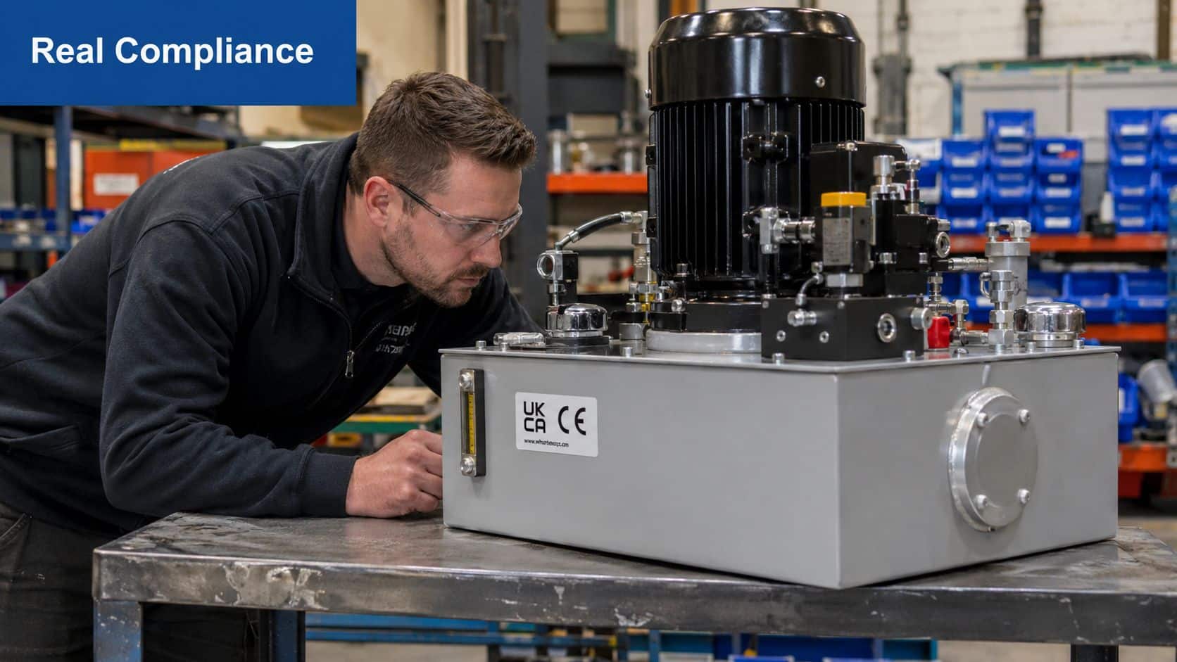
A new hydraulic power pack arrives on site. The nameplate is fitted, the paperwork pack looks tidy, and there's a CE or UKCA mark on the assembly. The temptation is to book it in, pipe it up and move on. That's where costly mistakes start.
Anyone who's spent time around bespoke hydraulic assemblies knows the gap between declared compliance and verified compliance. A sticker tells you something. It doesn't tell you everything. It doesn't confirm that the relief valve is set where the design says it should be, that the motor rotation is correct, that the hose build matches the drawing, or that the tank was kept clean enough during assembly to avoid an early failure.
On the shop floor, compliance verification is not paperwork administration. It's risk control. It stops you commissioning a unit with the wrong manifold, the wrong pressure switch, a missing guard, a non-traceable pressure-bearing part, or a wiring error that only shows up once the machine is under load. Those are the faults that trigger rework, delays, warranty disputes and, in the worst cases, unsafe operation.
For bespoke power packs and assemblies, the discipline has to go beyond collecting Declarations of Conformity and filing them away. The process needs to link documents, inspection, testing, serialisation and sign-off into one evidence trail. That's the part many teams skip when schedules tighten.
Beyond the Sticker Your Introduction to Real Compliance
A power pack can look finished and still be only half verified. That's common with one-off builds, retrofit assemblies and urgent replacement units where everyone is focused on delivery date first and evidence second. The trouble appears later, usually during commissioning or after handover.
Paper compliance and physical proof are not the same thing
A declaration may say the assembly meets the required rules. The workshop still needs to prove the actual unit in front of you matches the declared design. On hydraulic equipment, that means checking the fitted parts, the pressure capability, the functional behaviour, the markings and the traceability of anything safety-critical or pressure-bearing.
That difference matters because a bespoke hydraulic assembly isn't just a bag of compliant parts bolted together. The compliance burden often sits at assembly level. A correctly marked valve and a correctly marked motor don't automatically make the complete power pack compliant once they're mounted, piped, wired and configured as one system.
Practical rule: Treat the sticker as the start of compliance verification, not the end of it.
The UK's Office for Statistics Regulation offers a useful model for thinking about this. It defines accredited official statistics as a subset of official statistics that have been independently reviewed, which places external scrutiny and traceable evidence at the centre of trust and governance in the UK system, as set out in its guide on assessment and compliance checks for statistics producers. The hydraulic equivalent is straightforward. Verification is strongest when it produces a traceable evidence trail, not a one-off tick box.
What fails in practice
The weak process is easy to recognise:
- Documents are accepted at face value without checking whether they apply to the exact build.
- Incoming inspection is rushed because the supplier is known and the job is urgent.
- Testing is treated as a formality rather than an attempt to expose faults before site installation.
- Records are fragmented across emails, test sheets, phone photos and someone's memory.
The stronger process looks more disciplined:
| Stage | Weak habit | Better habit |
|---|---|---|
| Receipt | File the paperwork | Match documents to the exact serialised assembly |
| Inspection | Quick visual once-over | Verify BOM, markings, build quality and safety features |
| Testing | Run it briefly | Pressure, leak and functional test against written criteria |
| Records | Keep whatever arrives | Build a controlled compliance file |
Why this matters for bespoke power packs
A bespoke pack introduces interfaces, and interfaces are where errors hide. Pressure settings, motor data, coupling selection, filtration, return routing, cooling arrangements, guards, cable entries and control logic all interact. If you only verify at component level, you miss the system-level faults that matter most in service.
That's why compliance verification needs to be built like a workshop process. It has to survive staff changes, delivery pressure and awkward jobs. If it only works when your most experienced engineer is standing there, it isn't sufficiently resilient.
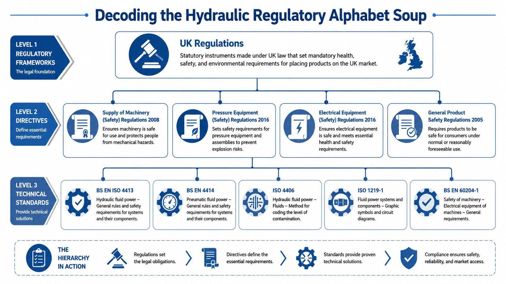
Decoding the Hydraulic Regulatory Alphabet Soup
Hydraulic engineers in the UK usually aren't short of regulations. The primary challenge is deciding which ones apply to the component, which ones apply to the assembly, and which standards you use to prove the design was sensible in the first place.
Start with the assembled product, not the loose parts
If you're buying a valve, a hose, a manifold block or a pump, you verify that item against the rules that govern that type of product. If you're building or integrating a power pack, you also have to assess the complete assembly as equipment in its own right.
That usually means separating the question into three layers:
-
Product marking and conformity
Is the supplied item correctly marked and declared for the market where it will be placed? -
Pressure-related obligations
Does the equipment or any part of it fall under pressure equipment requirements, and if so, how was that handled? -
Machinery and system safety
Does the completed assembly create mechanical, hydraulic, electrical or control-system hazards that need to be managed at assembly level?
What UKCA and CE marking actually tell you
For many engineers, UKCA or CE becomes shorthand for “safe and compliant”. That's too broad. Marking tells you the manufacturer has declared conformity to the applicable legislation for that product. It doesn't replace your own verification that the delivered item is the right one, correctly built, correctly configured and suitable for your duty.
On a hydraulic power pack, the mark may relate to the complete assembly. On a cartridge valve or pressure switch, it may relate only to that part. The distinction matters when you're integrating multiple items into one bespoke unit. Once you create a new assembly, the compliance question shifts upwards.
A useful parallel sits outside hydraulics. In sectors where traceable product identification matters, such as ensuring compliant medical device identification, the label is only one part of the control system. The same mindset works well on hydraulic assemblies. Marking has to tie back to records, specifications and verifiable build data.
The regulations engineers usually trip over
For most UK hydraulic assemblies, these are the rules and standards that deserve direct attention:
-
Supply of Machinery requirements
These govern the safety of machinery and assemblies that create functional and safety hazards once put into service. For a power pack, think guarding, emergency stopping where relevant, safe maintenance access, stability, instructions and system-level risk reduction. -
Pressure Equipment requirements
These become relevant where pressure-bearing parts and assemblies cross into regulated territory rather than remaining within sound engineering practice. The practical mistake is assuming all hydraulic items are treated identically. They aren't. -
Electrical compliance for the drive and controls
Motor, starter, enclosure, wiring and protection arrangements need checking against the intended supply, environment and installation method. -
Harmonised or recognised technical standards
These aren't just paperwork references. They're the working design rules many engineers rely on to show the system has been thought through properly.
A declaration with the wrong product description or the wrong standard references is often your first warning that nobody has checked the assembly carefully.
Standards that should shape your workshop thinking
For hydraulic systems, ISO 4413 sits near the centre of good practice because it addresses hydraulic fluid power system safety and general rules. In workshop terms, it pushes attention towards pressure limitation, isolation, energy control, cleanliness, identification and safe maintenance.
A simple way to organise the regulatory picture is this:
| Level | What you ask |
|---|---|
| Assembly level | Is the complete power pack safe, documented and correctly marked? |
| Pressure level | Are pressure-bearing items appropriately assessed and supported by evidence? |
| Component level | Do the individual parts match the specification and claimed conformity? |
| Standard level | Does the design follow recognised hydraulic safety practice? |
When engineers get into trouble, it's rarely because they've never heard of the rules. It's because they applied component logic to an assembly problem.
Supplier Qualification and Document Scrutiny
Good compliance verification starts before the crate is opened. If the supplier can't provide clear, relevant, consistent documents, that's already a technical warning. Hydraulic faults and document faults often travel together.
Don't confuse document quantity with compliance quality
One common failure in compliance work is completion-rate bias. A high rate of submitted documents gets mistaken for low risk. Guidance from Comply warns that training or completion figures alone don't demonstrate compliance success, and that stronger programmes use multiple evidence streams such as exam results, control testing and monitoring findings, as outlined in its article on measuring success in a compliance programme. On hydraulic assemblies, the equivalent is simple. A Declaration of Conformity on its own isn't enough. It needs support from test certificates, material traceability and evidence that the actual build matches the declared design.
What to read on a Declaration of Conformity
A DoC should answer basic technical questions cleanly. If it doesn't, stop there and query it.
Check for these points:
- Exact equipment description. The declaration should identify the assembly or product clearly enough that you can match it to the delivered item.
- Relevant legislation and standards. They should make sense for the product type. A vague list that looks copied from another job is a red flag.
- Manufacturer identity. You need a real legal entity behind the declaration, not just a trading name on a packing note.
- Authorised signatory. Someone must have accepted responsibility for the declaration.
- Issue control. Revision status and date matter when assemblies evolve during build.
Supporting evidence that carries real weight
A hydraulic compliance file is stronger when the DoC is backed by hard evidence. Depending on the assembly, that may include:
- Material certificates for pressure-bearing parts where traceability matters.
- Pressure test records for manifolds, pipework or completed assemblies.
- Hose assembly certificates tied to the actual hose build.
- Component datasheets that confirm pressure rating, compatibility and intended duty.
- Wiring and schematic documents that match the unit as built.
A practical way to manage collection and review is to use structured forms rather than chasing ad hoc emails. Teams that want a standardised intake process often use online data collection templates to gather serial numbers, certificates, drawing references and sign-off points in one format.
Qualify the supplier, not just the product
A compliant item from an unreliable supplier still creates operational risk. Qualification should include the supplier's ability to produce consistent evidence, respond to technical queries and control changes properly.
Ask questions such as:
| Supplier check | Why it matters |
|---|---|
| Can they provide controlled drawings and revisions? | Prevents build drift and substitution disputes |
| Do they keep traceability on pressure-bearing parts? | Supports fault investigation and due diligence |
| Can they show routine test records? | Tells you whether testing is embedded or improvised |
| Do they handle deviations formally? | Prevents undocumented substitutions |
| Do they understand assembly-level compliance? | Important for bespoke packs, not just loose components |
If your supply chain includes recurring custom builds, it's worth formalising expectations through a vendor process rather than relying on memory and inbox searches. A structured approach to vendor relationship management helps keep document requirements, approval status and corrective actions visible across repeat orders.
A tidy certificate pack from an unknown marketplace seller should never carry the same weight as a controlled document set from a supplier who can explain the build, the tests and any deviations.
Your Hands On Inspection and Testing Process
Here, compliance verification either becomes real or falls apart. Paperwork tells you what should exist. Inspection and testing tell you what arrived.
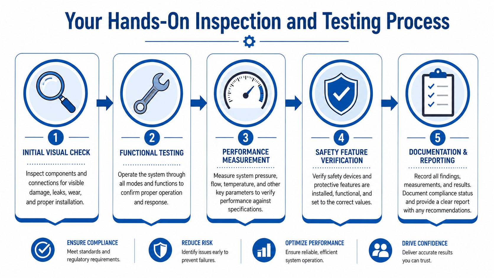
Stage one, confirm the build before applying power
Start with an unrewarding but essential task. Compare the delivered assembly against the bill of materials, general arrangement, hydraulic schematic and any customer-specific notes.
Look for mismatches in:
- Part numbers on pumps, valves, motors, switches and filters
- Port sizes and thread forms on suction, pressure, return and drain lines
- Nameplate data including serial number, voltage, power and working pressure
- Physical orientation of manifolds, coolers, gauges and service access points
- Safety hardware such as guards, covers and warning labels
This catches many expensive errors before the unit is energised. Wrong motor voltage, wrong pump displacement, missing drain connection or inaccessible filler breathers are classic workshop oversights.
Stage two, inspect workmanship and assembly detail
A bespoke power pack can pass a casual visual check and still be badly assembled. Inspect it like someone else will have to maintain it six months from now.
Focus on:
- Weld quality and finish on tank fabrication and brackets
- Pipe and hose routing for abrasion, bend radius and support
- Fastener security including locking method where vibration is expected
- Cable entry and gland selection for the operating environment
- Labelling on ports, controls and adjustment points
Poor routing and poor identification often show up together. If the build team was casual about one, they may have been casual about the other.
A useful mindset here comes from data quality work. If you want a simple explanation of why structured checking matters, NanoPIM's data validation resource is a good parallel. The principle is the same in a hydraulic workshop. You define what correct looks like before you decide the unit is acceptable.
A documented commissioning sequence also helps stop steps being skipped under time pressure. If your process needs a clearer handover from build to test, a defined set of commissioning procedures can keep inspection, testing and sign-off aligned.
Stage three, pressure and leak testing
This is the point where weak assemblies start to reveal themselves. The test arrangement must be safe, controlled and suitable for the circuit under test. Use calibrated instruments, isolate non-test items where needed and make sure everyone involved understands the hazards of stored hydraulic energy.
The plan note for this article specifies a practical benchmark that many engineers recognise on the shop floor: test to 1.5x maximum working pressure for a static pressure test. That only works if the test setup, components and safety controls are appropriate for that duty. The exact method must always match the design basis and applicable requirements for the assembly.
During the test, watch for:
- Visible leakage at fittings, manifolds, hose ends and instrument points
- Pressure decay that suggests leakage or component instability
- Distortion or movement in brackets, pipe runs or mountings
- Unexpected noise such as cavitation, bypass chatter or relief instability
Keep a camera or tablet at the rig. Photos taken during test setup and at any failure point often settle disputes faster than emails do.
Later in the process, it helps to show technicians what a disciplined approach looks like in motion:
Stage four, functional testing under controlled conditions
Once static integrity is proven, verify that the system behaves correctly. Don't stop at “motor runs and pressure builds”.
Run through the functional sequence:
- Check motor rotation before sustained running.
- Confirm pump prime and suction performance.
- Operate each valve function and compare response to the schematic.
- Set and verify relief pressure against the design requirement.
- Check instruments and switches for correct indication and changeover.
- Confirm return flow behaviour and watch tank condition during operation.
If the assembly includes solenoid valves, interlocks or sequence functions, test them in the same order the machine will use them. Many faults only appear in sequence.
Stage five, cleanliness and final condition
Hydraulic systems don't forgive dirt. Verification should include fluid cleanliness control and evidence that the reservoir, hoses and components were protected during build and test. If your acceptance basis specifies an ISO 4406 cleanliness code, measure and record it. If it doesn't, you still need a defined cleanliness expectation rather than a vague visual judgement.
Final checks should include fluid level, breather condition, cap security, spare ports, protection on exposed threads and the condition of any customer-facing documentation packed with the unit.
Defining Acceptance Criteria and Ensuring Traceability
Testing without written acceptance criteria produces arguments, not evidence. The test might have been done properly, but if nobody wrote down what constitutes a pass, the result becomes subjective the moment there's a leak, a pressure drift or a disputed setting.
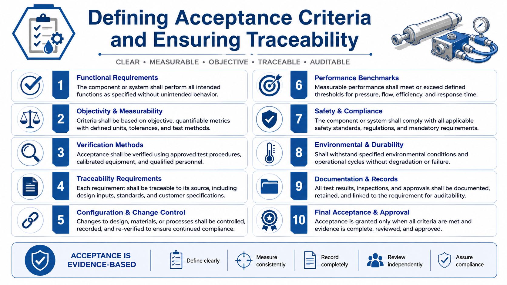
Write criteria that an inspector can actually use
Good acceptance criteria are observable and specific. “Unit tested and satisfactory” is useless. “No visible leak at the defined test condition” is far better. “Relief valve set to design requirement and locked” is better again if your process records the actual measured result and who set it.
For bespoke hydraulic assemblies, useful criteria often cover:
- Identity. The serial number, drawing issue and BOM revision match.
- Build conformity. Fitted parts match the approved design or a documented concession.
- Pressure integrity. The assembly completes the required pressure test without unacceptable leakage or instability.
- Functional behaviour. Each operating function performs as intended.
- Safety features. Guards, labels and isolation points are fitted and usable.
- Documentation pack. Required certificates, schematics and records are present and linked.
Stop relying on one headline pass rate
A practical model from Kusari's policy-compliance guidance is to move away from a single pass or fail and use tiered targets. It defines compliance rate as compliant items divided by total evaluated items, multiplied by one hundred, and recommends 95%+ for critical policies, 85%+ for important policies, and 70-80% for best-practice policies in its guide to policy compliance rate. In a hydraulic environment, that thinking is useful because it stops teams treating a missing cosmetic label the same way as a failed safety-critical pressure test.
A simple workshop interpretation looks like this:
| Control type | Example on a power pack | How to treat failure |
|---|---|---|
| Critical | Pressure integrity, relief protection, guarding | Hold the unit. No release |
| Important | Correct labelling, functional sequencing, document completeness | Correct before dispatch unless formally approved |
| Best practice | Cosmetic finish, non-critical layout preferences | Record and improve, but assess risk sensibly |
Build the traceability chain into the unit itself
Every bespoke pack should have a unique serial number on the nameplate. That number needs to lead directly to the build record. If it doesn't, traceability is only decorative.
A proper compliance file should connect the serial number to:
- the approved drawing set
- supplier declarations and certificates
- incoming inspection records
- pressure and functional test results
- photos of the completed unit
- concessions or deviations
- final release sign-off
That file is what protects you later. It supports fault finding, maintenance planning, warranty investigation and customer queries. It also makes repeat builds more consistent because engineers can see exactly what was done on the previous unit.
Where records have to be located quickly years later, documentation management becomes part of compliance verification, not just administration. Hydraulic schematics, pressure test sheets and replacement part references are much more useful when they're tied to one serialised assembly record.
If a unit fails in service and you can't trace its exact build state, your compliance process was never finished.
Troubleshooting Non Conformance and Getting Support
Even a solid process will uncover failures. That isn't a sign the process is broken. It's proof that it worked before the unit reached site.
Common non-conformances on hydraulic assemblies include wrong fitted components, leaking adapters, missing identification, absent certificates, poor hose routing, incorrect relief settings and drawing mismatches. The mistake is to fix them informally and carry on without preserving the evidence.
Use a short, disciplined response:
- Quarantine the item so it can't be issued or installed by mistake.
- Record the failure clearly with notes, photos, serial number and drawing reference.
- State the requirement that wasn't met. Be precise.
- Notify the supplier with evidence rather than a vague complaint.
- Agree corrective action and decide whether rework, replacement or concession is acceptable.
- Update supplier history so the issue informs future qualification.
This last point matters. Verification shouldn't be treated as a one-off gate. Guidance on compliance monitoring from ProviderTrust highlights the importance of matching verification frequency to source-update frequency, with monthly checking used in cases where source data updates monthly, in its discussion of the impact compliance spectrum. The practical lesson for hydraulic supply chains is that a non-conformance is also a data point about supplier reliability. If a supplier repeatedly misses traceability, markings or test evidence, your review cadence for that supplier should tighten.
A bulletproof compliance verification process doesn't depend on trust alone. It depends on evidence, repeatable checks and a clear route for dealing with anything that falls short.
If you need practical help with compliance verification for hydraulic components, bespoke power packs or complete assemblies, contact MA Hydraulics Ltd. The team can help you review specifications, check documentation expectations and avoid common verification mistakes before they turn into rework. Phone 01724 279508 today, or send us a message.
