
A machine can have plenty of hydraulic power and still feel wrong. The boom snatches instead of gliding. A clamp closes too hard, then stalls. A press reaches position, then hunts around it. In most of these cases, the pump and actuator aren’t the fundamental problem. Control is.
That’s where the hydraulic valve controller earns its keep. It tells the valve when to open, how far to open, how fast to move, and in better systems, whether the spool has gone where it was told. If hydraulics provide the muscle, the controller provides judgement.
For anyone specifying, integrating, or maintaining hydraulic systems in the UK, that distinction matters. Mobile plant, agricultural machinery, industrial power packs, and automated production equipment all depend on the same basic truth. Force without control wastes energy, shortens component life, and makes operators lose confidence in the machine.
The Brains Behind Brawn Introducing the Hydraulic Valve Controller
A hydraulic valve controller sits between the electrical command and the hydraulic valve’s mechanical movement. It takes a low-power input from a switch, PLC, joystick, HMI, or machine ECU and turns it into a controlled actuation signal for the valve. That might be a simple energise or de-energise command, or it might be a carefully managed current signal that positions a spool with fine resolution.
If you’ve ever worked on a system that looked healthy on the pressure gauge but behaved poorly in service, you’ve already seen why controllers matter. A cylinder doesn’t just need oil. It needs the right oil flow, at the right moment, in the right amount.
The UK has deep roots in this area. In the mid-19th century, British engineer Fleeming Jenkin developed the world’s first pressure-compensated flow control valve, a milestone that laid the groundwork for modern hydraulic control. That UK-originated technology enabled precise control and boosted productivity by an estimated 20 to 30% in early hydraulic cranes and presses used in places such as Manchester and Newcastle, according to this history of hydraulic valve development.
That history still matters because the engineering problem hasn’t changed. We’re still trying to make heavy hydraulic power behave predictably.
Practical rule: When a machine feels rough, don’t only ask whether the pump is producing pressure. Ask how the valve is being told to behave.
A good starting point is understanding the wider circuit first. If you want a quick refresher on the fundamentals behind pressure, flow, and load, this explanation of how hydraulics work is useful before you get deeper into controllers.
Exploring the Main Types of Hydraulic Valve Controllers
Not every hydraulic valve controller does the same job. Some switch a valve on and off. Others let you meter flow smoothly. The most advanced systems constantly compare commanded position with actual spool position and correct errors in real time.
The easiest way to separate them is to think in terms of switching, modulating, and correcting.
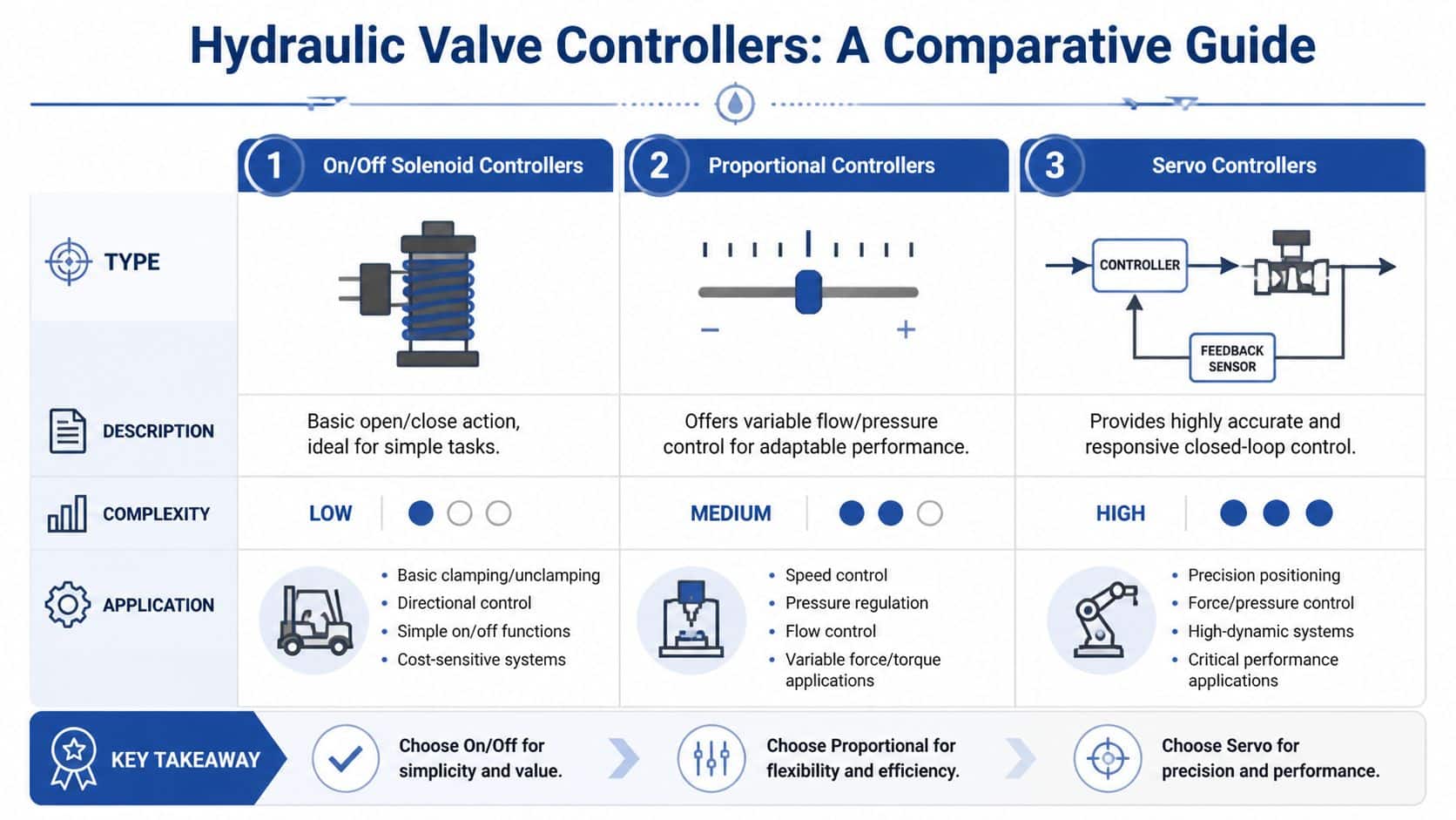
On off solenoid controllers
An on/off controller is the hydraulic equivalent of a wall light switch. The signal is either present or absent. The valve spool moves to one state or the other.
That simplicity is exactly why these controllers remain common. For a tipper body raise, a basic clamp release, or a straightforward directional function, on/off control is often the right choice. Fewer parameters means easier setup and fewer tuning headaches.
The limitation appears when the machine needs finesse. If an operator wants to feather a function, reduce shock loading, or synchronise movement with another axis, on/off control quickly shows its limits.
Proportional controllers
A proportional controller behaves more like a dimmer switch. Instead of fully open or fully closed, it lets you command intermediate spool positions. That allows controlled changes in flow, pressure, or both, depending on valve design.
Many engineers begin by discussing smoothness. A proportional valve can ramp a conveyor drive, soften a lifting function, or give an agricultural machine finer metering during repeated duty cycles. In UK mobile equipment, this kind of control is often the practical balance between capability and cost.
The controller matters as much as the valve. A poor command signal makes a good proportional valve look bad.
Servo controllers
Servo control sits at the high-precision end. It doesn’t just issue a command and hope the valve follows. It uses feedback, very tight control logic, and rapid correction to keep the spool where it should be.
That makes servo systems suitable where motion quality and repeatability matter more than simplicity. Test rigs, aerospace-type actuation, and highly coordinated industrial machinery often fall into this category. In many ordinary mobile applications, though, servo can be more complexity than the duty requires.
A common mistake is buying the most sophisticated controller available when the application only needs stable proportional control and sensible tuning.
A quick comparison
| Comparison of Hydraulic Valve Controller Types | ||||
|---|---|---|---|---|
| Controller Type | Control Principle | Typical Application | Precision | Cost |
| On/off solenoid | Binary energise or de-energise | Simple directional tasks, basic machine functions | Low | Low |
| Proportional | Variable electrical command gives variable valve response | Mobile machinery, industrial speed and force control | Medium to high | Medium |
| Servo | Closed-loop high-response control with feedback | High-accuracy motion and test systems | Very high | High |
The valve body itself also shapes what the controller can achieve. CETOP directional valves, modular valves, and inline circuit valves all behave differently in service, so it helps to understand the hardware side alongside the controller side. This guide to types of hydraulic valves is a useful companion when you’re matching control strategy to valve architecture.
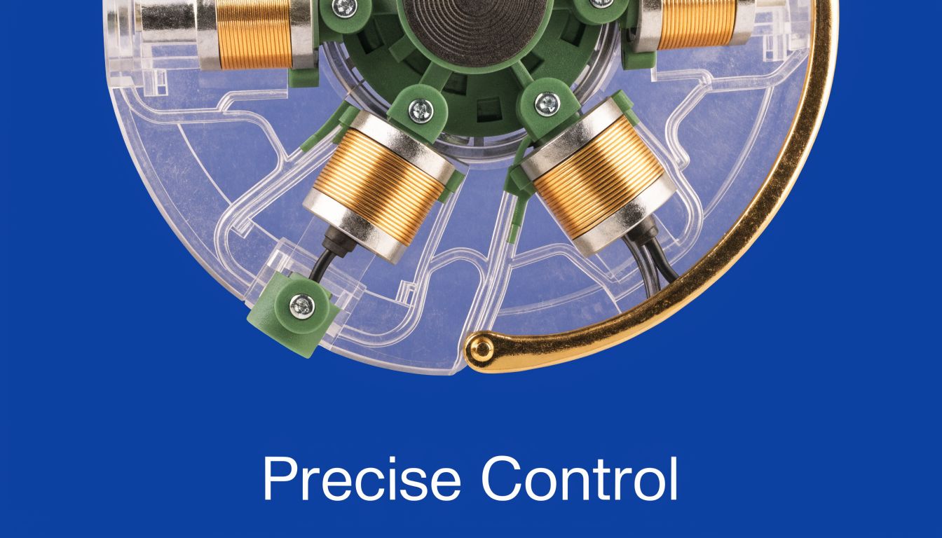
How Hydraulic Valve Controllers Achieve Precision Control
Precision starts with one basic question. Is the controller merely sending a command, or is it checking whether the valve obeyed it?
That’s the difference between open-loop and closed-loop control.
Open loop and closed loop
In an open-loop arrangement, the controller sends an electrical signal and assumes the valve responds as expected. This can work well in simple systems, especially where duty cycles are predictable and accuracy demands are modest.
Closed-loop control adds feedback. The controller measures actual spool position, compares it with the target, and adjusts the output to reduce the error. That constant correction is why closed-loop systems feel more stable and repeatable in demanding applications.
A useful analogy is vehicle steering. Open loop is like turning the wheel once and assuming the car has taken the corner correctly. Closed loop is what you do on the road. You keep watching the lane and making corrections.
Why current matters more than voltage
A proportional solenoid doesn’t behave like a simple resistive load. Coil resistance changes with temperature, so a fixed voltage won’t always produce the same magnetic force. That’s why proportional valve control relies on current-based signalling, often using Pulse Width Modulation, or PWM.
According to this explanation of proper control current for proportional valves, current ranges typically span 1.0 to 2.0 amps according to most manufacturers, with higher ranges used for larger flow-rated valves and hotter operating conditions. The same source notes that PWM induces less heat to the coil and enhances valve performance, while voltage can become limiting and prevent full resolution.
If PWM feels abstract, this short guide on industrial actuator PWM explained gives a helpful plain-language view of what the signal is doing.
Field insight: When a proportional valve works well cold but becomes inconsistent later, don’t only suspect contamination. Check whether the controller is regulating current properly.
The role of LVDT feedback
Modern electrohydraulic directional control valve technology uses advanced spool position control with closed-loop feedback and LVDT, or linear variable differential transformer, position sensors. An LVDT tells the controller where the spool is located, not where it was told to go.
That distinction is important. Spool friction, oil condition, temperature, and load changes can all shift actual valve behaviour. Feedback lets the controller compensate instead of drifting.
A short visual explanation helps here:
What improved electronics changed
Modern electrohydraulic valve technology also uses stepper motors, pressure reducing valves, and full closed-loop controls with LVDT sensors. According to this overview of directional control valve technology, these electronic control methods have improved flow accuracy significantly, while pressure compensation and flow regeneration help smooth operation and reduce parasitic losses in closed-centre load sense systems.
That’s why modern hydraulic valve controller design isn’t just about energising a coil. It’s about managing thermal behaviour, signal quality, spool feedback, and hydraulic dynamics as one system.
Selecting the Right Controller for Your Application
Choosing a hydraulic valve controller is rarely a matter of asking for the “best” one. The right choice depends on the machine’s job, the control platform around it, and how forgiving the application is when conditions drift.
For a procurement manager, that means writing a sensible specification. For an engineer, it means avoiding a mismatch between control ambition and hydraulic reality.
The market context shows why this matters. The UK industrial valve market exceeded £1.2 billion in 2025, with power-operated control valves making up 55% of production. In UK agriculture, 76% of hydraulic systems rely on advanced valve controllers for precision flow, and these can reduce fuel consumption by 15 to 20% in machinery such as tractors and harvesters, according to this hydraulic valve market analysis.
Start with the job, not the catalogue
A controller for an industrial press line and a controller for a compact agricultural machine may both be labelled proportional, but they won’t necessarily belong on the same machine.
Industrial environments often prioritise repeatability, PLC integration, and stable duty cycles. Mobile machinery often adds vibration, weather exposure, operator variability, and tighter packaging. If you start with the product family instead of the duty, you can end up paying for features you won’t use, or missing the resilience you need.
Questions that narrow the choice
Use these as specification questions rather than sales questions.
-
How precise does the movement need to be: If the function only needs positive switching, on/off may be enough. If the operator must feather movement or vary speed under load, proportional control is the usual next step. If the system must track position with very high accuracy, feedback-based control becomes more attractive.
-
What is the command source: A factory system may expect PLC analogue outputs or field-integrated electronics. A mobile machine may use joystick commands, machine controllers, or vehicle-based communications. The controller has to fit the wider electrical architecture, not just the valve coil.
-
What does the environment do to electronics: Heat, shock, moisture, and contamination all change what “suitable” means. A tidy indoor skid can tolerate arrangements that would become unreliable on a tractor, telehandler, or trailer-mounted power unit.
-
How serviceable must it be: Some users need a highly integrated module. Others need something a field engineer can diagnose quickly with standard test gear.
Industrial and mobile applications need different thinking
| Application focus | What usually matters most | Typical controller direction |
|---|---|---|
| Industrial machinery | Repeatability, integration with automation, predictable tuning | Proportional or closed-loop electrohydraulic |
| Mobile plant | Durability, compact packaging, operator feel, simpler serviceability | On/off or proportional depending on duty |
| Agriculture | Smooth metering, fuel efficiency, contamination resilience | Proportional with careful filtration and setup |
A procurement team will often focus on purchase price. That’s understandable, but it can miss where cost appears. If the controller causes harsh movement, operators compensate manually. If it’s awkward to tune, commissioning drags on. If diagnostics are poor, maintenance teams replace parts by guesswork.
Build a useful specification sheet
A practical controller specification should include:
-
Valve type and mounting standard
Identify whether you’re dealing with CETOP directional, proportional, modular, or inline circuitry. -
Electrical command details
Note supply voltage, expected signal type, and whether current control is required. -
Performance expectations
Define whether the machine needs simple actuation, smooth ramping, or true closed-loop positioning. -
Operating environment
Include vibration, ambient temperature, cleanliness risk, and whether the unit lives indoors or on mobile equipment. -
Maintenance expectations
Decide whether site teams need local adjustment, quick swap-out, or diagnostic access during fault-finding.
Buying a controller without writing down the machine’s control objective is how projects drift into expensive trial and error.
The better your specification, the easier it is to compare like with like.
Best Practices for Installation Tuning and Integration
A correctly selected hydraulic valve controller can still perform badly if it’s installed carelessly. Most field problems come from a small set of avoidable issues. Wiring errors, unstable mounting, poor cleanliness, and rushed tuning are the usual culprits.
Installation needs mechanical discipline and control discipline at the same time.
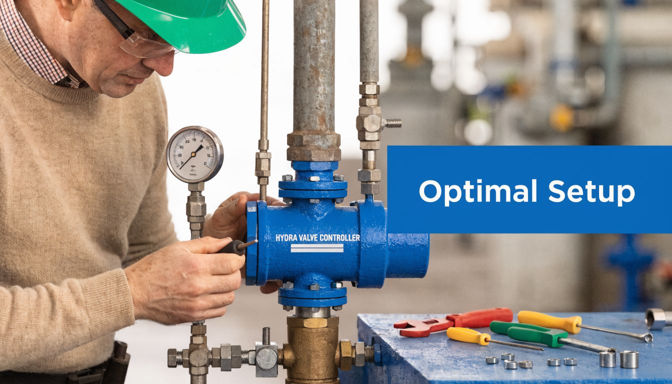
Get the physical installation right first
Before touching any tuning parameter, make sure the basics are sound.
- Mount the valve securely: Vibration changes behaviour and damages connectors over time. This matters even more on mobile machinery and retrofits.
- Check wiring against the actual controller pinout: Don’t assume all proportional controllers use the same logic or terminal arrangement.
- Protect signal quality: Route low-level control wiring sensibly and keep poor earth connections off the fault list from day one.
- Start clean and stay clean: Contamination is one of the fastest ways to turn a precision valve into an inconsistent one.
Fluid cleanliness isn’t an afterthought. It’s a prerequisite, particularly where spool clearances are tight and feedback control is involved. UK users dealing with agricultural retrofits should also keep BS ISO 4413:2010 in mind when managing hydraulic fluid cleanliness and safe hydraulic practice.
Why retrofits become unstable
Retrofitting modern controllers into legacy machinery often looks straightforward on paper. In practice, the controller may be far more capable than the machine’s original hydraulic behaviour will comfortably support.
A 2025 BFPA survey reported a 15% rise in hydraulic failures due to contamination in UK agricultural settings, and the same body of guidance notes that integrating controllers with LVDT feedback can introduce instability because valve dynamics create third-order transfer functions that limit controller gains. That makes retrofit tuning harder than generic guides often suggest, as discussed in this article on hydraulic proportional valve behaviour and contamination issues.
In plain terms, the valve, oil column, actuator, and load can start acting like a springy system. Increase gain too much and the machine hunts or oscillates.
Don’t tune a retrofit as if it were a clean-sheet design. Legacy pipework, actuator friction, and load variation all change the controller’s safe operating window.
A sensible tuning sequence
Commissioning goes better when you tune in this order:
-
Confirm basic hydraulic health
Verify pressure supply, return path, actuator condition, and absence of trapped air. -
Set neutral behaviour
Make sure the valve is stable at zero command. Drift at neutral will confuse every later adjustment. -
Introduce ramps before adding aggression
A well-chosen ramp often improves feel more than a high gain ever will. -
Increase gain gradually
Stop when the response is crisp but still settled. If the axis overshoots or chatters, back off. -
Use deadband compensation carefully
Too little compensation leaves sluggish response. Too much causes jumpy initial movement. -
Check hot behaviour, not only cold behaviour
A machine that tunes nicely on first start may behave differently once oil and coils warm up.
Integration with control systems
When the controller talks to a PLC, HMI, or machine ECU, define signal ownership clearly. Who handles the ramp. Who handles the fault state. Who decides what happens on power loss. If that logic is split across devices without a clear map, troubleshooting becomes slow and arguments start.
Industrial systems usually reward a documented I/O schedule and a parameter backup. Mobile systems reward sealed connections, simple diagnostics, and a setup that can be checked in the field without specialist software where possible.
A Guide to Troubleshooting and Proactive Maintenance
When a hydraulic valve controller starts misbehaving, many teams jump straight to replacement. That’s expensive, and it often misses the actual fault. A bad earth, dirty oil, sticky spool, or weak signal can make a healthy controller look defective.
A better approach is sequential. Check electrical input, then controller output, then hydraulic response, then fluid condition. Keep the steps in order.

What usually goes wrong
A proportional system that feels erratic doesn’t always have one dramatic failure. It often has a stack of smaller issues.
- Electrical command faults: Intermittent supply, damaged connectors, weak reference signals, or command scaling errors.
- Hydraulic contamination: Fine particles change spool movement long before anyone sees obvious external damage.
- Leakage at small openings: The machine may behave worst during low-speed control, where fine metering matters most.
- Poor filtration practice: Modern controllers need cleaner oil than many older systems were designed to maintain.
A 2025 UK Health and Safety Executive analysis found that 22% of manufacturing downtime was linked to proportional valve failures, often due to leakage or contamination. The same verified data notes that many UK industrial users experience 25% higher wear from poor filtration, failing to meet the 5-micron standards needed for modern controllers. Those findings point to a real maintenance gap, not just bad luck, as highlighted in this technical paper on control-system-related valve issues.
A practical fault-finding order
| Symptom | First check | Then check | Likely direction |
|---|---|---|---|
| No valve response | Power supply and enable signal | Coil current output | Electrical fault or controller inhibit |
| Jerky movement | Command stability | Fluid cleanliness and spool sticking | Signal issue or contamination |
| Slow response | Ramp settings | Pressure and flow availability | Parameter issue or hydraulic restriction |
| Unstable holding | Feedback integrity | Internal leakage and load effect | Sensor or valve wear issue |
This order matters because it prevents random parts swapping. If the command signal is wrong, changing the valve won’t help. If contamination is the cause, a new controller may appear to fix the issue briefly, then fail in the same way.
Predictive maintenance beats reactive replacement
The strongest maintenance programmes treat the hydraulic valve controller as part of the whole oil-powered system, not as an isolated electrical box.
Maintenance stance: If you only inspect controllers after the machine starts misbehaving, you’re already paying the penalty.
A proactive routine should include:
- Fluid monitoring: Trend cleanliness and watch for deterioration before performance complaints arrive.
- Filter discipline: Use filtration appropriate for modern proportional and feedback-controlled valves.
- Electrical inspection: Look for connector damage, water ingress, loose terminals, and cable strain.
- Functional testing: Periodically verify whether commanded response still matches actual machine behaviour.
- Pressure verification: Keep proper test equipment available. A hydraulic issue can look electrical very quickly.
For technicians who need to verify system pressure during diagnosis, a proper hydraulic pressure tester kit is one of the most useful tools in the workshop. It helps separate low-pressure supply problems from valve or controller faults before parts are removed.
What good maintenance changes
Good maintenance shortens diagnosis, reduces nuisance failures, and protects expensive components upstream and downstream of the valve. It also improves operator trust. People notice when a machine responds the same way every time.
That consistency is usually built in the workshop, not bought in a hurry after a failure.
Your Partner for Complete Hydraulic Control Solutions
A hydraulic valve controller looks like a component. In practice, it’s part of a control chain. The valve, coil, electronics, feedback method, fluid condition, filtration standard, actuator, and machine logic all shape the result.
That’s why the best outcomes usually come from treating control as an application problem rather than a part-number problem. A simple on/off function can be made reliable with disciplined installation. A proportional system can feel excellent with proper current control, clean oil, and patient tuning. A closed-loop setup can deliver impressive accuracy, but only if the hydraulic circuit and commissioning process support it.
For UK engineers, buyers, and maintenance teams, the practical questions are usually the same. Which controller type suits the duty. Which valve format will integrate cleanly. How much complexity is justified. How will the system be maintained once it leaves the drawing office.
Where specialist support matters
A specialist hydraulic supplier is most useful when it does more than ship parts. Good support means helping the customer match components, avoid poor substitutions, and build complete assemblies that make sense in service.
That’s especially important when dealing with:
- Cross-references for older machinery
- CETOP directional and proportional valve selection
- Compact mobile power requirements
- Bespoke manifolds and integrated assemblies
- Industrial power pack builds that need tested compatibility
What a complete solution usually includes
| Contact MA Hydraulics Today |
|---|
| Technical advice on hydraulic valve controller selection |
| Support with valves, manifolds, filters, pumps, couplings and related components |
| Hydronit mini power pack assembly to customer specification |
| Bespoke industrial power packs up to 11 kW |
| Help with hard-to-find parts and practical cross-references |
For many buyers, a key benefit is reducing uncertainty. Instead of sourcing the controller from one place, the valve from another, and then discovering an avoidable integration issue on site, it’s far better to work with a team that understands the complete hydraulic package.
That matters whether you’re replacing a failed valve assembly on a mobile machine, specifying a new industrial unit, or trying to retrofit modern control into equipment that was never designed with today’s expectations in mind.
A well-matched hydraulic valve controller won’t just make a machine move. It will make the machine behave.
If you need help choosing components, cross-referencing parts, or building a complete hydraulic control package, contact MA Hydraulics Ltd. Phone 01724 279508 today, or send us a message.
