
A brake that only works on paper is worse than no brake at all. In the field, the problem shows up fast. A loaded winch creeps when the engine stops. A lift platform settles a few millimetres every few minutes. A conveyor on an incline won’t hold position during a power cut, so operators chock it manually and hope nothing shifts.
That’s usually where the important conversation starts. Not “which motor is cheapest?” but “what will hold, stop, and release properly in this application without causing the next failure?”
Motors with brake solve that problem when they’re specified correctly. They give you controlled stopping, reliable holding, and a safer response when power or pressure disappears. They also create plenty of avoidable trouble when the brake type, torque margin, release method, or duty are guessed rather than engineered.
The Critical Role of Control in Hydraulic Systems
Loss of control in a hydraulic system rarely looks dramatic at first. More often, it starts with nuisance faults. A machine won’t stay parked on a gradient. A slewing function drifts. A materials handling unit hesitates because the brake releases late, then the operator compensates with throttle and shock-loads the drivetrain.
Those are warning signs. Left alone, they turn into damaged couplings, overheated oil, worn friction surfaces, bent shafts, and unsafe workarounds on site.
Where uncontrolled movement causes real trouble
The applications are familiar across UK industry and mobile equipment:
- Winches and hoists need the load to stay where it was left, especially after shutdown or pressure loss.
- Inclined conveyors must resist back-driving when product mass tries to turn the drive in reverse.
- Wheel and track drives on plant need parking and holding functions that don’t rely on operator timing.
- Rotary and positioning functions need the shaft to stop where commanded, not coast past.
A motor without the right braking arrangement can still run the machine. It just can’t be trusted when the load starts driving the system instead of the other way round.
Uncontrolled movement is rarely a motor problem alone. It’s usually a system problem that shows up at the motor first.
The wider market reflects how important this has become. The industrial motor brakes market is projected to grow from USD 1,472 million in 2024 to USD 2,529 million by 2035, at a projected 5.1% CAGR. That growth is tied to safety, automation, and the need for tighter control in industrial systems.
Why this matters to UK engineers
In practice, UK engineers aren’t short of component options. They’re short of application-specific guidance. Generic catalogue data won’t tell you whether the brake will hold on a cold morning, release cleanly with your actual line pressure, or survive repeated stop-start cycles in a dirty agricultural environment.
That’s why motors with brake need to be treated as part of the full hydraulic function, not an accessory bolted onto the end of a drive.
Defining Motors with Brakes in Hydraulics
A motor with brake in hydraulic work isn’t a single magic component. It’s a drive assembly made up of a hydraulic motor and a braking mechanism that either holds the shaft stationary, slows it in a controlled way, or does both depending on the design.
When engineers talk about motors with brake, they often mean one of two jobs:
- Holding brake. Stops rotation and keeps the shaft from moving when the machine is at rest.
- Braking during motion. Helps decelerate a moving load in a controlled way.
Those jobs sound similar, but they aren’t interchangeable. A brake that holds perfectly once stopped may be a poor choice for repeated dynamic stopping if its thermal capacity and wear characteristics don’t suit the duty.
Static holding versus dynamic braking
This distinction matters more than most catalogues suggest.
A static or holding brake is there to lock position. Think of a conveyor on an incline, a parked wheel drive, or a raised platform that must not creep down after shutdown. The brake’s main duty is resisting torque once the shaft is stationary.
A dynamic brake deals with motion. It helps bring a rotating system down to speed safely and predictably. In hydraulic systems, that can involve the mechanical brake itself, the hydraulic circuit, or both working together.
If you ask a holding brake to do repeated dynamic stops without checking heat and wear, it’ll often glaze, drag, or lose consistency. If you try to use hydraulic deceleration alone where a load must remain fixed after pressure loss, the machine may drift because there’s no positive holding function.
What fail-safe really means
The term fail-safe gets used loosely. In practical engineering terms, it means the brake moves into the safe state when power or pressure is lost.
The most common example is a spring-applied brake. Springs force the brake on. Hydraulic or electrical power releases it during normal operation. If supply disappears, the brake applies automatically.
That’s the right logic for many hazardous or load-holding duties because the machine doesn’t depend on the operator reacting quickly enough.
Practical rule: If loss of pressure or electrical supply could let the load move on its own, start with a fail-safe brake concept and work from there.
Common brake arrangements in hydraulic use
You’ll usually see these arrangements in the field:
- Spring-applied brakes for parking and holding duties where safe engagement on power loss is required.
- Hydraulically released brakes when the machine already has a suitable pressure source and controlled release matters.
- Hydraulically applied brakes where service braking during operation is the main requirement.
- External brake packages fitted to the motor or gearbox input/output where packaging or service access drives the design.
The right choice depends on what the machine must do when everything is working, and equally, what it must do when something stops working.
Key Applications for Hydraulic Brake Motors
The easiest way to decide whether you need motors with brake is to ask a blunt question. If pressure vanished right now, would the load stay safe and controlled?
If the answer is no, a brake usually isn’t optional.
Winches, hoists, and lifting functions
A lifting system is the clearest example. The load can become the driving force the moment the operator stops commanding motion. Relying only on hydraulic restriction or valve leakage performance is risky if the function has to remain fixed during shutdown or a fault.
Brake motors in these systems are used to:
- Hold suspended or raised loads when motion stops
- Prevent reverse rotation when the load tries to overrun the motor
- Support controlled lowering when paired properly with the valve arrangement
The key mistake is assuming the brake alone manages the whole event. It doesn’t. The valve logic, pressure control, and load-induced behaviour still have to be engineered as a system.
Wheel drives and mobile plant
On self-propelled equipment, the brake duty often blends parking, holding, and machine security. That includes compact plant, agricultural equipment, and recovery systems where the machine may sit on a slope or carry a shifting load.
In those applications, the brake has to work in conditions that are less forgiving than a clean indoor installation:
- Contamination
- Shock loading
- Variable operator behaviour
- Intermittent use followed by long idle periods
That changes what “good enough” looks like. A compact brake package may fit neatly on paper but still be the wrong answer if it’s difficult to inspect, awkward to release, or too sensitive to wear adjustment.
Inclined conveyors and processing equipment
Inclined conveyors are where poor brake selection gets expensive quickly. Product mass can back-drive the drivetrain, especially at shutdown. If the holding torque margin is weak, the conveyor rolls backwards, and the damage isn’t limited to the motor. Belts, couplings, and product handling all suffer.
In fixed industrial settings, motors with brake also support:
- Indexing and stopping accuracy in transfer systems
- Safer shutdown behaviour during power loss
- Reduced creep while operators load, unload, or clear the machine
A brake here isn’t just a safety component. It affects uptime and maintenance workload.
Positioning, productivity, and energy use
There’s a second reason to specify properly. Control quality affects cycle time and operating cost. A machine that stops cleanly and releases consistently is easier to run at speed without shocking the system.
The efficiency argument is stronger than many buyers expect. Properly specified motors with brakes can deliver energy savings of 12 to 15% over standard configurations, while system-level use of VFDs for torque control can improve efficiency by over 50% in certain applications. That evidence comes from brake motor applications more broadly, but the engineering principle carries over. When braking, torque control, and stopping behaviour are matched properly to duty, the system wastes less energy and usually suffers less wear.
A brake that releases cleanly and stops predictably often improves throughput as much as it improves safety.
Comparing Hydraulic Brake Technologies
No brake technology is “best” in the abstract. Each one solves a different problem and introduces a different compromise. The wrong choice usually comes from mixing up holding duty with service braking duty, or from valuing compact packaging over maintainability.
Spring-applied hydraulically released brakes
This is the workhorse for fail-safe holding. Springs apply the brake. Hydraulic pressure releases it. If pressure disappears, the brake engages.
Best for load holding, parking, anti-runaway protection, and applications where the safe state is “stopped and held”.
What works well
- Positive holding without depending on operator input
- Good fit for mobile and industrial systems where safety on power loss matters
- Straightforward operating logic
What catches people out
- The brake needs reliable release pressure every time
- Poor line sizing or sluggish release circuits can cause drag
- Repeated dynamic stopping can create heat and friction wear if the brake was only sized as a holder
Hydrostatic or dynamic braking through the hydraulic circuit
This approach uses the hydraulic system itself to slow the motor. Flow restriction, controlled metering, and circuit design manage deceleration.
Best for smooth slowing during motion, especially where mechanical wear needs to be reduced.
Advantages
- No friction lining wear in the same way as a mechanical brake
- Smooth control when the valve strategy is correct
- Useful for deceleration before a holding brake takes over
Limitations
- It doesn’t give positive holding by itself
- Heat goes into the hydraulic system, so oil condition and thermal management matter
- If pressure is lost completely, the system may not hold position unless a separate brake is present
Wet disc brakes
Wet disc units package multiple friction surfaces in oil. They’re often chosen where compactness, torque density, and heat handling matter.
Best for heavier-duty environments with repeated braking and limited installation space.
They tend to suit harsh service better than more exposed designs because the oil environment helps with cooling and contamination control. The trade-off is complexity. If access is poor or the unit is buried in a larger assembly, diagnosis and service become less convenient.
External shoe or drum brakes
These sit outside the motor and act on a drum or similar surface. They’re less compact but often easier to inspect visually.
Best for applications where service access and simple mechanical inspection matter more than tight packaging.
A common advantage is maintainability. A common disadvantage is exposure. Dirt, moisture, and general site contamination affect external brakes more readily than enclosed alternatives.
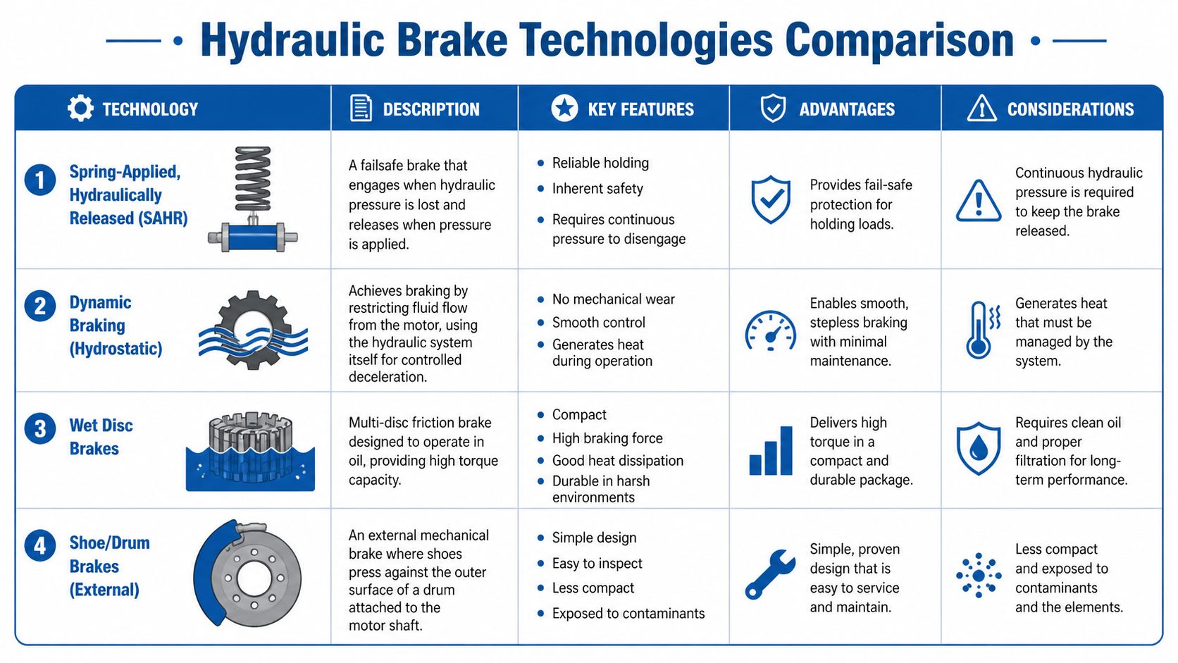
A practical comparison
| Brake technology | Strongest use case | Main benefit | Main drawback |
|---|---|---|---|
| Spring-applied, hydraulically released | Parking and fail-safe holding | Safe engagement on pressure loss | Can drag if release circuit is poor |
| Hydrostatic dynamic braking | Controlled deceleration | Smooth stopping with low mechanical wear | No positive holding on its own |
| Wet disc brake | High-torque repeated braking | Compact and durable | More complex service access |
| External shoe or drum brake | Accessible mechanical systems | Easy inspection | Less protected from contaminants |
Don’t ask one brake to do every job. Use the hydraulic circuit for controlled deceleration where appropriate, and use the mechanical brake for positive holding where the risk demands it.
Your Specification and Selection Checklist
Most brake motor failures are specification failures. The unit may be built correctly, installed correctly, and still perform badly because the original assumptions were wrong.
That’s especially common in UK agricultural and mobile work, where real operating conditions vary far more than the catalogue duty suggests. HSE data from 2025 indicates that 15% of UK farm hydraulic failures stem from inadequate holding torque during power loss, and lack of region-specific guidance often leads to 20 to 30% higher OEM costs through over-specification that still doesn’t solve the safety issue.
Start with the load, not the motor
A lot of buyers start by looking at motor frame size or shaft detail. That’s too late in the process.
First establish:
- What is trying to move the shaft? A suspended load, gravity on an incline, reflected inertia, or stored energy in the driven system.
- When must the brake act? Parking only, emergency stop, normal stopping, or all three.
- What happens on power loss? Hold immediately, allow controlled run-down, or switch to another safe state.
If the machine can be back-driven, the brake torque requirement is driven by the load path through the transmission, not by the motor’s nameplate alone.
Separate holding torque from stopping duty
In this regard, many specifications go off course. Holding torque answers one question. Stopping duty answers another.
Use these distinctions:
- Holding torque must exceed the torque trying to turn the shaft when stationary.
- Dynamic braking requirement depends on speed, inertia, deceleration rate, and frequency of stops.
- Thermal capacity decides whether the brake survives repeated operation without fade or excessive wear.
A brake that will hold a static load may still be unfit for repeated starts and stops on a fast cycle machine.
Check the duty cycle honestly
Engineers often underestimate how often the brake works. Operators use a machine differently from how the original design intent reads.
Look at the duty:
- Frequent inching or indexing increases heat and wear.
- Long hold periods favour stable static holding performance.
- Shock loading from abrupt reversals or abrupt release can damage couplings and friction surfaces.
- Outdoor service adds moisture, dirt, and corrosion concerns.
If the motor sits in a dirty agricultural or materials handling environment, seal quality and release consistency matter as much as torque rating.
Build safety requirements in early
A brake is often part of a safety function, not just a mechanical convenience. That means the release and engagement logic must match the machine risk assessment.
For UK users, the practical questions include whether the arrangement supports the required performance level logic under standards such as BS EN ISO 13849-1, and whether the brake must engage automatically under fault conditions. That decision should be made before procurement, not during commissioning when everyone realises the control philosophy doesn’t match the machine’s risk.
If the brake is part of the machine’s safety case, treat it as a safety device from day one. Don’t retrofit the logic afterwards.
Pay attention to interfaces and packaging
You can have the right brake and still create a poor assembly.
Check:
- Shaft type and fit
- Flange compatibility
- Available envelope for brake housing
- Manual release access if fitted
- Hydraulic port orientation
- Service access for inspection and replacement
This matters even more if you’re pairing the unit with high torque hydraulic motors or reduction gear, because reflected loads and installation space can change quickly once the full assembly is modelled.
Brake Motor Specification Checklist
| Parameter | Key Question / Calculation | MA Hydraulics Tip |
|---|---|---|
| Load type | Is the load suspended, overrunning, inclined, or shock-prone? | Define what drives the shaft during failure, not only during normal running. |
| Holding torque | What torque must the brake resist when the system is stationary? | Calculate from the driven load path through the gearbox or transmission. |
| Dynamic duty | Does the brake stop motion, or only hold after hydraulic deceleration? | Don’t assume a holding brake is suitable for repeated service braking. |
| Duty cycle | How often does the brake engage and release in normal operation? | Ask operators and service teams, not just the machine designer. |
| Thermal load | Will repeated stops build heat faster than the brake can shed it? | Frequent cycling usually needs a more robust braking strategy. |
| Release method | Is release hydraulic, electrical, or mechanical, and is it reliable on site? | Slow release causes drag, heat, and operator complaints. |
| Safety logic | What must happen during power or pressure loss? | Match the brake state to the machine’s required safe condition. |
| Mounting and access | Will the unit fit properly and remain serviceable once installed? | Leave room for inspection and fault-finding. |
| Environment | Is the machine exposed to dirt, water, fertiliser, vibration, or corrosion? | Outdoor and agricultural service usually punishes marginal sealing. |
| Maintenance plan | How will wear, drag, and release performance be checked over time? | A good specification includes a realistic inspection routine. |
Integrating Brake Motors into Your Hydraulic System
Once the brake motor is selected, the next problems are usually integration problems. A good component can still underperform if the release line is poorly arranged, the gearbox ratio is mismatched, or the power pack doesn’t support the control sequence cleanly.
Match the brake motor to the transmission
The brake doesn’t work in isolation. Gear reduction changes what the brake “sees” at the shaft, and it changes the load’s tendency to back-drive.
For UK applications using AC gear brake motors, adding a gearbox can increase torque from 35 Nm to 700 Nm on a 1.1 kW motor, and the DC electromagnetic brake should provide holding torque greater than 200% of dynamic torque to resist back-driving. That’s a useful benchmark for conveyor and industrial drive thinking because it shows how quickly output conditions move away from the base motor figures.
In hydraulic systems, the same principle applies. Once reduction stages, wheel diameters, drum diameters, or chain drives are included, the required holding performance can look very different from the motor’s direct output torque.
Get the release circuit right
A brake that doesn’t release fully creates drag. Drag creates heat. Heat creates wear and operator complaints.
Check these points during integration:
- Brake release pressure arrives before significant drive torque
- Return flow doesn’t trap pressure and delay engagement
- Hose and fitting sizes support prompt brake response
- Any sequencing logic is tested under cold oil conditions
- Manual release arrangements are accessible and understood
Many “weak motor” complaints are brake release issues. The motor is fine. The brake is half-on.
Pairing with power packs and motor-pump assemblies
Brake motors often work alongside compact hydraulic assemblies where space is limited and response needs to be repeatable. That’s common on power pack driven machinery, mobile attachments, and bespoke industrial systems.
When integrating with a motor and pump hydraulic assembly, pay close attention to startup and shutdown sequence. If the brake releases too early or too late relative to pump output and valve state, the machine feels rough and components see unnecessary shock.
Commissioning checks that save trouble later
Commissioning shouldn’t stop at “it rotates”. Check actual behaviour under load.
A sensible site checklist includes:
- Hold test with the working load
- Release test after idle periods
- Hot condition check after repeated cycling
- Emergency stop observation for unwanted overrun
- Power loss behaviour to confirm the machine moves to the intended safe state
Most brake issues are found in the first proper loaded test. If you only commission unloaded, you’re delaying the failure until the customer does the testing for you.
Basic fault patterns to watch
Some faults repeat across applications:
| Symptom | Likely cause |
|---|---|
| Brake drags during operation | Incomplete release, trapped pressure, poor sequencing |
| Load creeps at rest | Holding torque too low, wear, or incorrect brake selection |
| Harsh stop or shock | Brake engaging before deceleration is controlled |
| Brake won’t engage consistently | Contamination, wear, release mechanism fault, or poor control logic |
| Excess heat near brake | Frequent dynamic use beyond intended duty |
Good integration is mostly about sequencing, pressure management, and honesty about the machine’s real operating pattern.
Source Your Solution with MA Hydraulics
Motors with brake aren’t difficult because the concept is complicated. They’re difficult because the application details matter. Holding duty, dynamic duty, release logic, gearbox effect, installation space, contamination risk, and safety behaviour all have to line up.
That’s why the cheapest part on a quote can become the most expensive part on the machine. If the brake drags, won’t hold, or engages harshly, the cost shows up elsewhere. In downtime, callouts, worn couplings, damaged drivetrains, and operators working around a system they no longer trust.
MA Hydraulics supports UK engineers, OEMs, agricultural operators, and MRO teams that need the answer to be practical, not theoretical. The business supplies hydraulic components and bespoke power solutions for mobile and industrial applications, including gear motors, valves, flow dividers, gearboxes, couplings, clutches, manifolds, and custom power pack assemblies. For broader component support and complete system requirements, see the hydraulic equipment supply range at MA Hydraulics.
For projects involving motors with brake, that matters because the brake decision is rarely isolated. It usually connects to the power pack, the gearbox, the valve arrangement, the control logic, and the service conditions on site.
If you’re replacing a failed assembly, reviewing a persistent drift problem, or designing a new machine that must hold and stop reliably, getting the specification right at the start saves time and repeated rework later.
If you need help selecting or integrating motors with brake, contact MA Hydraulics Ltd. Phone 01724 279508 today, or send us a message.
