A common job starts with a machine that still runs, but no one trusts it. Flow has gone soft when the oil gets warm. The original pump number no longer cross-references cleanly. The operator wants it quiet, procurement wants it quickly, and maintenance wants something that will not come back on a pallet in six months.
That is where the internal gear pump earns its keep. In the right duty, it is not a compromise part. It is the pump you fit when you want steady delivery, civilised noise levels, good behaviour with viscous fluids, and predictable service life. In UK industrial, agricultural, and mobile plant work, those qualities matter more than brochure language.
Most engineers already know the basic category. The harder part is choosing the right design for the specific job, then keeping it alive in mud, heat, contamination, cold starts, and long idle periods. That is where selection discipline matters more than theory.
Why Your Hydraulic System Needs a Reliable Workhorse
An OEM engineer specifying a compact power unit and an MRO manager replacing a failed pump usually face the same question. Do you fit the cheapest unit that matches the shaft and ports, or do you fit the pump that suits the fluid, pressure pattern, and duty cycle the machine sees?
In many UK applications, the answer points to an internal gear pump. Materials handling kit, agricultural machines, and industrial hydraulic packs often need smooth delivery without the harsher pulsation you get from more basic arrangements. They also need a pump that will prime sensibly, tolerate thicker oils, and not turn the machine into a noise complaint.
The market direction tells the same story. The UK internal gear pump market expanded from $0.59 billion in 2023 to $0.63 billion in 2024, with a 6.9% CAGR, and is projected to reach $0.83 billion by 2028, according to this UK internal gear pump market analysis. That growth reflects how widely these pumps are used across industrial, mobile, and agricultural hydraulic systems.
Where they make sense
Internal gear pumps are a practical fit when the job calls for:
- Steady flow: Useful where actuator movement needs to feel controlled rather than choppy.
- Low noise: Important on indoor plant, workshop equipment, and operator-adjacent machinery.
- Viscous fluid handling: Helpful where the oil grade, temperature swing, or process fluid would punish a less suitable pump.
- Compact packaging: Especially in smaller hydraulic power units and mobile assemblies.
Where engineers get caught out
The pump itself is rarely the whole problem. Most failures blamed on the pump started earlier, with poor suction conditions, wrong viscosity, contamination, or an optimistic pressure assumption.
Practical takeaway: An internal gear pump is a workhorse only when the installation supports it. Good suction plumbing and clean oil matter as much as the catalogue rating.
That is why selection has to go beyond displacement and flange pattern. The details decide whether the pump becomes a dependable asset or another recurring stores item.
The Core Operating Principle How Internal Gear Pumps Work
The easiest way to picture an internal gear pump is as two intermeshing wheels turning inside a close-fitting housing, with a crescent-shaped separator controlling where fluid can and cannot go. It is a positive displacement design. Each revolution traps a fixed volume and carries it from inlet to outlet.
What the rotating parts are doing
The larger internal gear acts as the rotor. The smaller gear, often called the idler, sits eccentrically inside it. The two do not spin in open space. The crescent seal separates the inlet side from the discharge side and stops fluid from short-circuiting back across the pump.
That layout gives the pump its character. Instead of flinging fluid around, it traps fluid in the spaces between the gear teeth and the casing, then carries it around the crescent until the teeth mesh again on the outlet side.
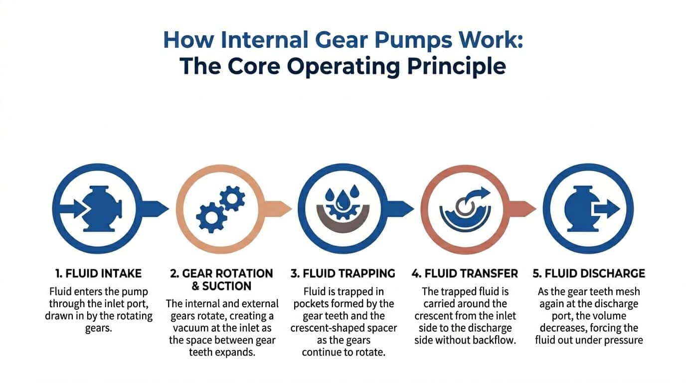
One full pumping cycle
The cycle is straightforward, but the small clearances are doing serious work.
-
Unmeshing at the inlet
As the gears rotate apart on the suction side, the cavity volume increases. That creates the low-pressure area that draws fluid into the pump. -
Fluid trapped in pockets
The incoming fluid fills the spaces between the teeth and the casing. Those pockets are sealed well enough to move a fixed volume per revolution. -
Transfer around the crescent
The fluid travels around the casing. The crescent prevents it from slipping straight back to the inlet. -
Meshing at the outlet
As the gear teeth come back together on the discharge side, the cavity volume reduces. The fluid is forced out under pressure.
Why the flow is so smooth
This is one of the main reasons engineers choose the design. Because of the geometry of the rotor, idler, and crescent seal, the pump produces smooth, non-pulsating flow. According to this technical explanation of internal gear pump operation, that arrangement can keep noise below 75 dB(A) at 3000 rpm, and helical gear variants can cut noise and pulsation by 30%.
In practice, that matters more than many datasheets admit. Noise is not only an operator comfort issue. It often reveals how hard the pump is being driven, how the oil is behaving, and whether the rest of the hydraulic circuit is civilised or not.
Tip: If a machine has to work near people for long shifts, a quieter pump can be worth the extra thought up front. The system tends to sound better because the flow is steadier, not because someone added more guarding.
Why self-priming matters
Internal gear pumps are also valued because they are self-priming. That does not mean they forgive poor installation. It means the pump can establish suction without needing the sort of manual priming routine that slows commissioning.
That feature helps on mobile equipment, tank-mounted units, and machinery that may stand idle before restart. It is still not an excuse for long, undersized, or leaky suction lines. Self-priming helps a good installation. It does not rescue a bad one.
The role of clearances
Engineers sometimes focus on gears and forget the housing. Internal gear pumps live or die by controlled clearances. Too loose and the pump slips internally, especially as pressure rises. Too tight and hot oil, thermal growth, or debris can drive friction and wear.
That is why a good internal gear pump feels simple from the outside and exacting from the inside. The design works because every feature supports controlled displacement with minimal backflow.
Key Types and Technical Specifications for UK Applications
Not every internal gear pump belongs in every hydraulic system. The useful distinctions are not marketing labels. They are direction of rotation, pressure capability, housing material, displacement range, and how the pump behaves with the fluid you intend to use.
For engineers reviewing replacement options or planning a fresh build, the technical conversation usually starts at the pump group and ends at the duty cycle.
The main design variants
The standard configuration for most hydraulic duties is the crescent-seal internal gear pump. This is the format most engineers picture when discussing industrial and mobile hydraulic service.
You will also encounter reversible and unidirectional versions. That choice matters on mobile machinery, winch circuits, and any arrangement where shaft rotation or flow direction may reverse during operation. Reversible pumps are useful, but they are not a free upgrade. They bring packaging and sealing considerations that must match the circuit.
Then there is the housing and construction question. In harsher work, especially agriculture and industrial service, cast iron bodies are often preferred because they cope better with sustained pressure, structural load, and rougher operating conditions.
The specifications that matter
A pump data sheet can be crowded, but a few values do most of the selection work.
Displacement in cc per revolution
Displacement tells you how much fluid the pump moves per shaft revolution before losses. It is the starting point for working out flow at a given motor or engine speed.
For hydraulic engineers, this is the practical number because it links directly to actuator speed, cycle time, and power unit sizing. If the machine needs controlled low-speed movement, displacement and speed need to be considered together, not separately.
Pressure rating in bar
Pressure rating has to be read properly. There is a difference between continuous duty pressure, intermittent peaks, and what the rest of the circuit allows.
Some hydraulic internal gear pumps used in UK applications sit comfortably in mainstream industrial pressure ranges. Others are designed for more demanding duty. The trap is selecting by relief valve setting alone rather than by true operating pressure pattern.
Speed in rpm
Speed affects suction behaviour, noise, wear, and how forgiving the pump is with colder or thicker fluid. A pump that looks correct on paper can become difficult in service if the drive speed is too ambitious for the inlet conditions.
Lower speed often helps with viscous fluid handling and suction stability. Higher speed may suit compact packaging, but it narrows your margin if the tank, pipework, or strainer arrangement is marginal.
Viscosity in cSt
Internal gear pumps often make sense here. They are well suited to fluids ranging from relatively thin to very viscous service conditions, provided the design and speed match the duty.
Viscosity is never a static figure in the field. UK ambient conditions shift cold-start behaviour. A system that feels fine in a warm workshop can become reluctant on a winter morning. For that reason, engineers should always think in terms of start-up viscosity, normal running viscosity, and hottest expected viscosity.
Matching specification to application
The right pump for a compact hydraulic unit is not automatically right for a farm machine or a factory line. Selection needs context.
- Industrial power packs: Usually favour stable flow, low noise, and predictable continuous operation.
- Agricultural machinery: Needs better tolerance of contamination risk, shock loads, and outdoor temperature swings.
- Mobile plant: Often needs compact packaging, dependable suction behaviour, and careful attention to reversible or bidirectional requirements.
For teams comparing options across common hydraulic gear pump formats, this overview of gear hydraulic pumps is useful as a reference point for available configurations and product families.
A quick specification filter
| Specification | Why it matters | Common selection mistake |
|---|---|---|
| Displacement | Sets theoretical flow per revolution | Matching old part number without checking required flow |
| Pressure rating | Determines whether the pump survives the duty | Using peak pressure as if it were continuous duty |
| Speed range | Affects suction conditions and wear | Overspeeding on cold oil |
| Viscosity suitability | Governs starting, leakage, and efficiency | Selecting for warm oil only |
| Construction material | Influences durability and rigidity | Using a light-duty body in harsh service |
Selection note: If the machine spends much of its life hot, dirty, or heavily loaded, choose for the worst normal day, not the best commissioning day.
Performance and Efficiency: What to Expect in Practical Use
A pump may have the right displacement and still disappoint in service. That usually comes down to efficiency. Performance is the difference between theoretical flow and what the machine gets once pressure, leakage, heat, and friction enter the picture.
For internal gear pumps, the efficiency story is better than many people expect, especially in designs built to control internal leakage under pressure.
Volumetric efficiency under load
Volumetric efficiency is the key figure when an operator complains that the machine slows down as pressure rises. The usual cause is internal slip. As differential pressure builds, more fluid leaks back across clearances instead of going to the actuator.
Advanced internal gear pumps address that with a pressure-compensating sealing element. According to this engineering discussion of gear pump design and reliability, these pumps can achieve nearly pressure-independent volumetric efficiency of 74-88% above a threshold of 6-10 bar, and this design can reduce energy costs by 15-20% compared to non-compensated pump designs.
That matters in daily use. It means the pump can hold onto its output more consistently instead of feeling strong at low load and weak once the circuit starts working.
What operators notice
The first sign of a well-matched internal gear pump is not usually a gauge reading. It is machine behaviour.
Flow remains predictable
Actuators move with fewer surges. Lift and clamp functions feel more controlled. The pump does not sound like it is fighting itself every time pressure rises.
Noise stays civilised
A pump that delivers smooth flow tends to keep the rest of the system calmer. Valves, hoses, and mountings generally have an easier life when pulsation is lower.
Heat build-up is more manageable
When a pump leaks internally or runs outside its comfortable viscosity range, it turns more shaft power into heat instead of useful hydraulic work. Better control of internal leakage reduces that penalty.
What reduces real-world efficiency
Internal gear pumps are capable units, but they are not immune to poor system conditions.
- Hot, thin oil: Increases internal leakage across clearances.
- Cold, thick oil: Raises drag and can punish the suction side.
- Marginal inlet arrangements: Encourage cavitation and aeration.
- Dirty fluid: Wears the running surfaces that efficiency depends on.
- Wrong speed for the duty: Makes a good pump behave badly.
Reading the pump data effectively
A catalogue curve is useful, but only if you compare it with actual operating conditions. In practice, ask these questions:
- What is the oil viscosity at cold start?
- Where does the machine spend most of its life on pressure?
- Is the duty continuous, intermittent, or shock-loaded?
- Does the pump run fast because the drive package demands it, not because the fluid wants it?
Key takeaway: A good internal gear pump does not only make pressure. It maintains usable flow as pressure changes, what the machine feels.
When engineers assess pumps this way, efficiency stops being an abstract number and becomes what it should be. Stable cycle times, lower wasted energy, and a system that ages more gracefully.
Selecting the Right Pump A Comparison and Checklist
Choosing an internal gear pump should be a short technical exercise, not a guessing game based on flange shape and what is in stock. The pump must fit the machine, but it also has to fit the way that machine is used. Those are not always the same thing.
A replacement on a lightly used workshop unit can tolerate different compromises from a pump on a loader, baler, press, or continuous-duty pack.
Start with the job, not the old part
The old unit is a clue. It is not proof of correctness. Machines are often carrying a pump selected years ago around packaging limits, availability, or cost pressure.
A better selection process is:
-
Define the actual duty
Is it continuous industrial operation, intermittent mobile duty, or agricultural service with dirty surroundings and frequent cold starts? -
Confirm the fluid behaviour
Look at viscosity through start-up and normal running. Internal gear pumps usually reward careful thinking here. -
Check true pressure exposure
Not just the relief valve setting. Consider peaks, dwell at pressure, and whether reversals or shock loads are part of the cycle. -
Review inlet conditions
Tank position, suction hose length, bends, strainers, and lift all matter. -
Consider maintainability
Can the next engineer cross-reference seals, shafts, and mounting details without a detective story?
Pump type comparison for hydraulic systems
| Pump Type | Pressure Range | Flow Pulsation | Viscosity Handling | Complexity & Cost |
|---|---|---|---|---|
| Internal gear pump | Moderate to high, depending on design | Low | Very good with a wide range of fluids, including viscous service | Moderate to higher |
| External gear pump | Commonly used where simple, durable service is needed | More noticeable than internal gear designs | Better suited where fluid conditions are less demanding | Lower and simpler |
| Vane pump | Often chosen where smooth running is needed in cleaner systems | Low | More sensitive to fluid condition and wear issues | Moderate |
This is the trade-off in plain terms. If the fluid is awkward, noise matters, or the machine benefits from smoother delivery, the internal gear pump usually moves up the list. If the brief is simplicity and basic hydraulic duty at the lowest upfront spend, external gear designs still have their place.
Do not use old pressure assumptions
A lot of engineers still treat internal gear pumps as though they belong below the pressure levels now possible with newer designs. That is outdated.
Recent UK developments include separable crescent plates that can push internal gear pump pressures to 400+ bar, with 15-20% lifecycle cost saving in the right duty, as outlined in this research on advanced internal gear pump design. The practical lesson is not that every application should chase high pressure. Internal gear pumps should not be dismissed on assumptions carried over from older designs.
A field checklist before you place the order
For OEM design work
- Match displacement to required actuator speed, not just motor speed.
- Check the pressure profile across the full cycle.
- Specify shaft, flange, and porting clearly so service replacements remain realistic.
- Decide early on reversible or unidirectional operation.
For MRO replacement work
- Inspect the failed pump and the oil together. A damaged pump often tells you what the circuit has been doing.
- Check whether the machine was noisy before the failure. That usually points to suction or cavitation issues, not just wear.
- Confirm rotation direction at the machine, not from memory or faded labels.
- Cross-reference the application, not only the stamped part number.
On pricing
Actual market pricing varies by brand, construction, and configuration, so it is best handled by quotation rather than generic list assumptions. In practice, standard Group 0 to Group 3 hydraulic pumps usually sit in one price bracket, while specialised high-pressure or reversible variants sit higher. The important point is lifecycle cost. A pump that avoids repeated replacement, noisy running, or hot-oil inefficiency is often the cheaper unit over time even if the invoice says otherwise.
Selection tip: When a pump fails repeatedly, stop buying the same pump harder. Re-check the duty, suction side, contamination control, and pressure exposure.
Installation, Maintenance, and Troubleshooting
Most internal gear pump problems are set up before the first start. The pump then gets blamed for conditions it did not create. Installation quality, oil cleanliness, and suction-side discipline decide a large part of service life.
Installation habits that prevent trouble
The pump wants a clean, well-supported inlet path and correct alignment on the drive. Most avoidable damage starts with one of four issues.
- Poor suction plumbing: Long hoses, sharp bends, undersized line sizes, or blocked strainers increase inlet losses.
- Air ingress: A suction line can leak air inward without leaking oil outward.
- Dry starting: Internal gear pumps need fluid for lubrication from the start.
- Misalignment: A pump forced into position by the coupling will often fail at the shaft seal or bearings.
For repairable hydraulic units and service assessment, this overview of hydraulic pump repair covers the kind of support many maintenance teams need when a pump has already been damaged and the root cause still needs identifying.
Preventive maintenance that works
A sensible routine is not complicated. It just has to be consistent.
Watch the sound
Operators are first to hear a problem. A clean internal gear pump usually sounds steady. If it develops a harsh, rattling, or crackling note, investigate before the machine keeps running itself into a rebuild.
Check the oil thoroughly
Oil condition is not only about colour. Look for contamination, aeration, and signs of overheating. If the oil smells burnt or appears foamy, the pump may be suffering from circuit issues rather than internal defects alone.
Track temperature and behaviour
If a function becomes slow only after warm-up, suspect viscosity change and internal leakage. If it is worst at cold start, check suction conditions and whether the oil is too heavy for the speed.
Workshop rule: A pump that changes character sharply with temperature is telling you something useful. Listen to it.
Common failure patterns in UK service
UK-specific data is limited, but the pattern from field work is familiar. According to this gear pump troubleshooting reference used in service contexts, contamination from environmental conditions is a leading issue in agricultural and mobile plant use, and there was a 22% rise in gear pump replacements in the UK linked to cavitation, often caused by incorrect installation or suction blockages.
That aligns with what many engineers see in practice. Pumps on outdoor machinery do not live in laboratory oil. They live in dust, mud, water ingress risk, hurried hose changes, and tanks that are not always cleaned as thoroughly as they should be.
Troubleshooting by symptom
Low flow or weak function
Possible causes include worn internal clearances, hot thin oil, relief valve issues, or air on the suction side.
Start by checking:
- Oil level and condition
- Suction line restriction
- Rotation direction
- System pressure behaviour under load
Excessive noise
Noise often means cavitation, aeration, or mechanical distress.
Look for:
- Blocked suction strainers
- Collapsed hoses
- Loose fittings drawing air
- Pump speed too high for the inlet arrangement
Overheating
A hot pump may be bypassing internally, running against excessive restriction, or circulating poor-quality fluid.
Inspect:
- Relief valve setting and operation
- Oil viscosity at running temperature
- Internal wear signs
- Whether the machine is dwelling at pressure too long
A short visual explanation can help when training fitters or reviewing failure modes with site teams:
Cross-referencing and replacement reality
One of the harder MRO jobs is replacing an obsolete pump where the machine builder is long gone or the original code is incomplete. In those cases, engineers should capture the fundamentals before ordering:
- Mounting flange pattern
- Shaft type and diameter
- Port sizes and orientation
- Rotation
- Displacement
- Normal operating pressure
- Duty pattern
Cross-referencing works best when the replacement decision is based on those physical and hydraulic facts, not just catalogue resemblance. That avoids fitting a pump that bolts on neatly but behaves badly once the machine is loaded.
Partnering for Long-Term Hydraulic Success
A good internal gear pump earns its value over years, not on day one. It gives you smooth delivery, quieter running, and sensible performance with fluids and duties that are less forgiving than ideal bench conditions.
The gains come from making the right choice early. Match the displacement to the job. Respect viscosity across the full temperature range. Keep the inlet side generous and airtight. Treat contamination as a system problem, not only a filtration problem.
That is also why technical support matters. The most successful hydraulic projects usually come from engineers who combine product knowledge with application knowledge. They ask what the machine does, how often it runs, what the oil looks like after a season, and what failed last time. That process prevents expensive repetition.
For teams planning new systems, retrofits, or replacements, broader fluid power services can be as important as the pump itself. Selection support, cross-referencing, repair assessment, and complete power pack thinking often make the difference between a quick fix and a durable solution.
For expert advice on selecting the right internal gear pump for your application, or to discuss a bespoke hydraulic power pack, our technical team is ready to help. Phone 01724 279508 today, or send us a message at https://www.mahydraulics.co.uk/contact-us/.
If you need help specifying, replacing, or diagnosing an internal gear pump, contact MA Hydraulics Ltd. We can assist with application review, cross-referencing, and practical hydraulic component support. Phone 01724 279508 today, or send us a message at https://www.mahydraulics.co.uk/contact-us/.
