A machine usually gives you a warning before a pump fails outright. Lift functions slow off from cold. Steering feels lazy at low revs. A compact power pack starts running hotter on a duty cycle it handled comfortably a month earlier. The pump gets the blame first because it sits at the centre of the circuit and it is often the quickest component to point at.
On site, the root cause is often less dramatic. A gear hydraulic pump can be sound mechanically and still perform poorly if the inlet line is undersized, the shaft coupling is out, the rotation is wrong, or the displacement does not match the prime mover speed. That is the practical side of gear pump work. Simple construction does not give much tolerance for poor installation or a mismatched application.
That is also why gear pumps remain common across UK mobile plant, agriculture, materials handling, and industrial power units. They are compact, economical to package, and usually straightforward to replace or support in the field. At MA Hydraulics, we see the same pattern repeatedly with Vivoil and OMT units. The best results come from getting the basics right early, especially on machines that must work in dirty, wet, or stop-start conditions.
For engineers, operators, and maintenance teams, the pertinent questions are practical ones. Which pump type suits the duty. Which group size fits the space and drive arrangement. What flow will it deliver at the actual running speed, not just the nominal speed. And will it stay reliable on a UK machine that has to start cold, work hard, and keep going with minimal downtime.
The Unsung Hero of Your Hydraulic System
A gear hydraulic pump tends to get attention when output drops and the machine starts costing time. On a farm, that shows up as a loader that lifts slowly or steering that feels weak at idle. In a factory, it is often a support circuit that loses pace and starts upsetting cycle times.
The pump’s job is straightforward. It provides the flow the rest of the system depends on. If that flow is low, unstable, or badly matched to the duty, faults appear across the circuit and the pump often gets blamed before anyone checks speed, inlet conditions, oil viscosity, or drive alignment.
Where gear pumps earn their place
Gear pumps remain a practical choice across UK agriculture, mobile plant, materials handling, and industrial power units because they are compact, relatively simple to package, and usually easier to replace than more complex pump types. In the right application, they give dependable service with sensible maintenance demands.
That long service life is not accidental. Gear pumps have stayed common on British machinery because they suit typical operating conditions. Cold starts, dirty environments, stop-start duty, limited installation space, and field repairs all favour a pump that is mechanically simple and widely available.
At MA Hydraulics, that is the context we work in most often. Vivoil and OMT gear pumps are regularly specified for mobile and industrial duties where predictable flow, straightforward mounting, and parts support matter more than chasing a higher-cost solution that the machine does not need.
Why they still matter on modern equipment
Modern systems still use gear pumps for the same basic reason. They solve a lot of hydraulic jobs cleanly and economically. Auxiliary circuits, compact power packs, tipping gear, steering functions, lubrication systems, and general-purpose industrial duties all fall into that category.
This is significant because gear pumps are rarely specialist components. They are the everyday working units on machines that have to start in poor weather, run hard, and stay serviceable in the UK without long delays for replacement or overhaul.
Practical view: If the requirement is steady flow, manageable cost, simple installation, and reliable support, a gear hydraulic pump is usually one of the first options to assess properly.
How a Gear Hydraulic Pump Moves Fluid
The basic action is positive displacement. Two gears rotate inside a close-fitting housing. As the teeth come out of mesh on the inlet side, they create an expanding space that draws fluid in. As the teeth go back into mesh on the outlet side, they reduce that space and push fluid out.
A simple way to picture it is two interlocking water wheels running inside a sealed casing. They do not scoop fluid through the middle. They carry it around the outside of the gears, between the tooth spaces and the housing wall.
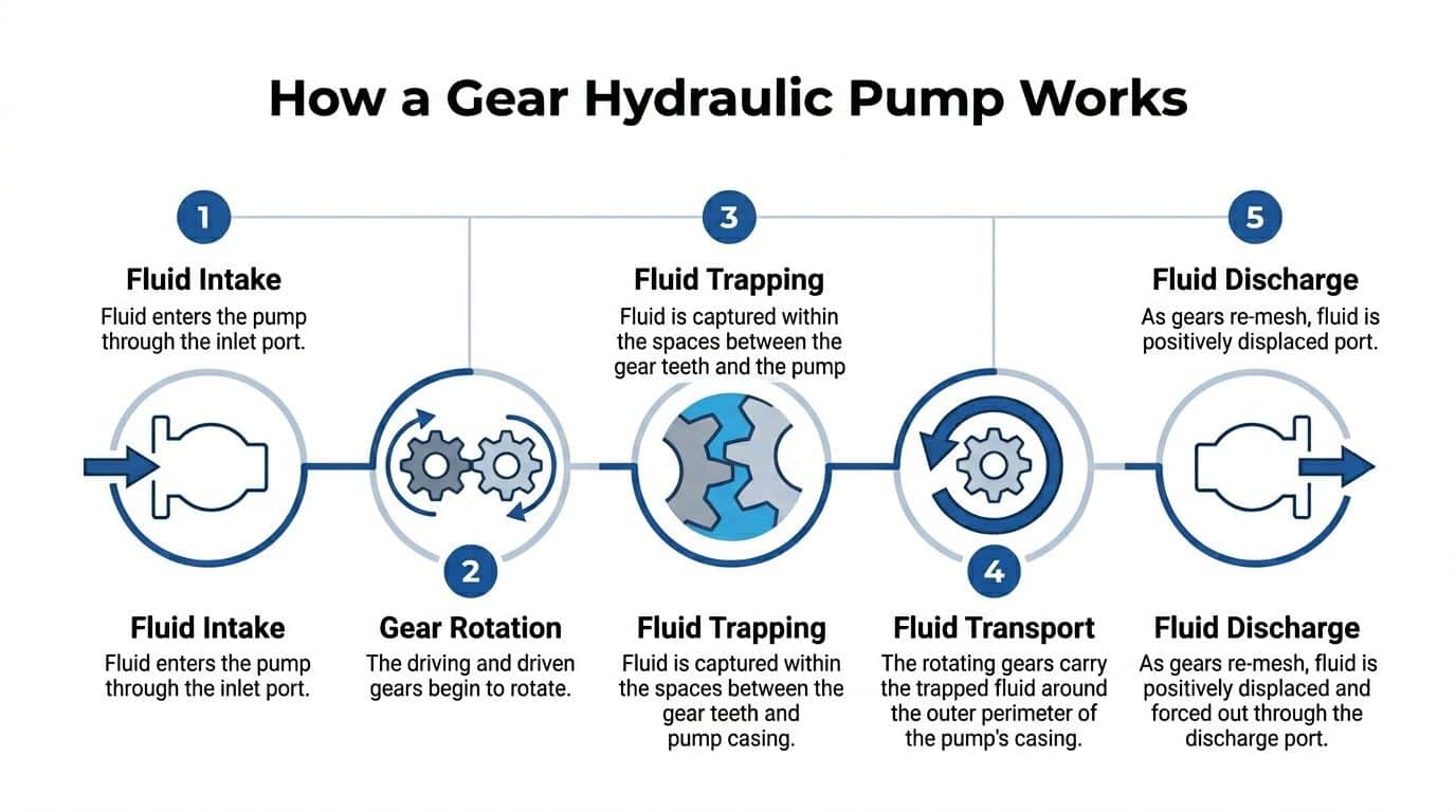
The five stages in plain terms
-
Fluid enters the inlet port
The gears begin to separate on the inlet side. That creates volume. The increase in volume lowers pressure locally and allows hydraulic oil to move into the pump. -
The gears rotate
One gear is driven by the shaft. It turns the other gear. The pair stay in mesh, which keeps movement synchronised. -
Oil becomes trapped in tooth spaces
Fluid sits in the spaces between the gear teeth and the pump body. It is not compressed at this stage. It is being carried. -
The oil travels around the casing
The rotating gears transport the trapped oil around the outer perimeter of the internal chamber. Fluid does not pass directly between the meshing teeth in the centre. -
The outlet side forces fluid into the circuit
As the teeth mesh again, the volume between them closes down. The oil has to go somewhere, so it is displaced into the outlet port and into the system.
What creates pressure
A pump creates flow first. Pressure appears when that flow meets resistance. A freely circulating line gives low pressure. A loaded cylinder, hydraulic motor, or restriction raises pressure because the pump is still trying to move oil into a harder-to-fill path.
This distinction matters in fault finding. A machine with poor function may not have a pressure problem first. It may have a flow problem caused by low pump speed, worn internals, poor inlet conditions, or the wrong displacement.
Three terms that matter on the workshop floor
-
Displacement
This is the amount of oil the pump moves each revolution, usually in cc/rev. Larger displacement means more flow at the same rpm. -
Flow
This is the volume delivered over time, usually in L/min. Flow affects actuator speed. -
Pressure
This is resistance to flow, usually in bar. Pressure relates to force and load handling.
Tip: If an attachment is moving too slowly, start with flow and drive speed. If it cannot lift or clamp under load, check pressure capability and relief settings after that.
Why simplicity matters
The reason gear pumps stay popular is that the operating principle is mechanically direct. There are fewer moving parts than in many variable-displacement designs. That does not make them suitable for every application, but it does make them attractive where dependable fixed flow is the priority.
For many mobile and industrial systems, that straightforward action is exactly the point. Less complexity often means easier replacement, faster diagnosis, and fewer surprises when the machine returns to service.
Decoding Gear Pump Types and Groups
Gear pump selection usually goes wrong on the hard details, not on the basic principle. Two pumps can look close enough on the bench, share a similar flange, and still be wrong for the machine because the rotation, shaft, port layout, or group size does not match the duty.
That matters every day on UK plant and industrial equipment. We see it regularly when a machine arrives with a pump that was chosen by appearance or old part-number cross reference alone, then shows noise, slow functions, or premature seal failure once it is back in service.
External and internal gear pumps
For most mobile machinery, power packs, and general industrial hydraulics, the standard choice is the external gear pump. It uses two meshing external gears inside a close-tolerance housing, gives fixed displacement, and is generally the most straightforward option for replacement, stocking, and service support.
An internal gear pump uses an inner gear running within an outer gear. These pumps have their place, but in mobile and agricultural hydraulics they are not usually a direct substitute for a standard external gear unit. If the machine was built around an external gear pump, treat internal gear designs as a separate engineering decision, not a quick alternative.
Unidirectional and reversible pumps
Rotation is one of the first checks, because getting it wrong can damage the pump quickly.
A unidirectional gear pump is designed for one specified direction of shaft rotation. The internal loading, port timing, and sealing arrangement are built around that direction. Install the wrong hand of pump and the result is often poor inlet filling, excess noise, low output, or immediate distress during commissioning.
A reversible gear pump is built for duties where the shaft may run in either direction and the hydraulic circuit is designed to suit that. These are common on certain attachments, specialist mobile systems, and some compact power units where bidirectional operation is required.
On the workshop floor, this is a simple but expensive mistake. The shaft turns, so the pump looks alive. The circuit performance says otherwise.
What the group size really tells you
Group size is a dimensional family, not a full performance specification. Group 0, Group 1, Group 2, and Group 3 indicate the general body size, mounting pattern, and displacement window you are dealing with. That makes group size useful for narrowing down what will physically fit, especially when matching stocked ranges such as Vivoil and OMT or specifying a replacement for a bespoke MA Hydraulics power pack.
It also helps set expectations. A Group 0 pump is usually chosen for compact auxiliary duties. A Group 3 unit is more likely where higher flow is needed and the installation space allows for a larger body and shaft.
Pressure still depends on the actual model, speed, oil viscosity, and duty cycle. If the application involves force calculations or relief setting checks, use a proper hydraulic pressure calculation method rather than relying on group size as a shortcut.
Standard Hydraulic Gear Pump Group Sizes at a Glance
| Group Size | Typical Displacement (cc/rev) | Typical Max Pressure (bar) | Common Applications |
|---|---|---|---|
| Group 0 | Approx. 0.25 to 2 cc/rev | Up to around 200 bar | Compact mobile equipment, mini power packs, auxiliary functions |
| Group 1 | Approx. 1 to 9 cc/rev | Up to around 250 bar | Small machinery, agricultural auxiliaries, light industrial circuits |
| Group 2 | Approx. 4 to 28 cc/rev | Up to around 250 bar | Tractor hydraulics, materials handling, general mobile plant |
| Group 3 | Approx. 20 to 60 cc/rev | Up to around 300 bar | Higher flow mobile systems, industrial power units, heavier duties |
These are practical ranges, not a substitute for the manufacturer datasheet. Some models sit outside them, and continuous-duty ratings are often lower than short intermittent limits.
What works in practice
A sensible selection process starts with the interface details:
-
Confirm the physical fit
Check flange, pilot, shaft type, shaft diameter, ports, and available envelope space. -
Confirm rotation and port arrangement
Left-hand versus right-hand errors are still common, especially on mobile equipment that has already been modified once. -
Check the operational duty
PTO speed, electric motor speed, relief setting, oil grade, ambient temperature, and cycle severity all affect whether the pump is suitable. -
Use the old pump as a reference, not proof
Machines get altered over time. A pump that was fitted previously may have been a compromise, or the wrong unit made to work badly.
The practical rule is straightforward. Group size gets you into the right housing family. Displacement, pressure rating, speed range, rotation, and mounting details decide whether the gear hydraulic pump will survive and perform properly.
Reading Pump Specifications and Performance Curves
Datasheets are useful only if they are read in the same way the machine will operate. A gear hydraulic pump can look correct on a parts list and still be wrong once rpm, pressure, and oil temperature are taken into account.

The core specification lines
Most pump datasheets revolve around a short set of key figures:
-
Displacement in cc/rev
This tells you how much oil the pump moves per revolution in ideal conditions. -
Pressure rating in bar
Usually split into continuous duty and intermittent duty. Continuous rating is what matters for the bulk of the working cycle. -
Speed range in rpm
Minimum, rated, and maximum speed all matter. Too slow can hurt inlet filling. Too fast can create inlet problems and heat. -
Port and shaft details
These matter for fit, alignment, and installation quality just as much as for specification.
Efficiency on real equipment
Efficiency is where the neat theory becomes workshop reality. Internal leakage, friction, and temperature all affect the result.
Expert operational data shows gear pumps achieve a near pressure-independent volumetric efficiency range of 74 to 88 percent when properly designed, provided differential pressure is around 6 to 10 bar or higher, according to Pumps & Systems on gear pump design, operation, and reliability.
That matters for two reasons. First, expected flow at the outlet is not always the same as theoretical flow from displacement and rpm. Second, heat generation changes as load and operating condition change.
Why curves matter more than catalogue shorthand
A performance curve gives a better picture than one headline figure. It shows how flow, power requirement, and efficiency behave across the operating window.
When reading one, focus on these points:
-
Find your operating speed
Start with the shaft speed the pump will see in service, not the ideal motor nameplate speed. -
Locate your expected pressure band
A pump feeding a lightly loaded auxiliary circuit behaves differently from one spending much of its life near the top of its pressure rating. -
Check expected delivered flow
Theoretical flow is only the first estimate. The curve helps you see what happens under load. -
Review power demand
The drive motor or PTO must handle the actual input demand, not just the target hydraulic output.
For anyone checking the relationship between pressure, area, and force in a hydraulic system, this guide on how pressure is calculated is a useful companion to pump selection work.
Practical tip: If a pump performs well when cold but falls away once the machine warms up, do not jump straight to relief valves. Check what the efficiency behaviour and thermal condition are telling you first.
What the curve does not excuse
Curves do not compensate for poor installation. A pump matched correctly on paper can still suffer from cavitation, aeration, or excessive case loading if the inlet line, coupling, and reservoir arrangement are poor. The curve shows potential performance. The system layout decides whether you get it.
How to Size and Select Your Gear Pump
Pump selection starts with the job, not the catalogue. You need to know what the machine must do, how fast it must do it, what pressure it will see in service, and what speed the prime mover can reliably provide.
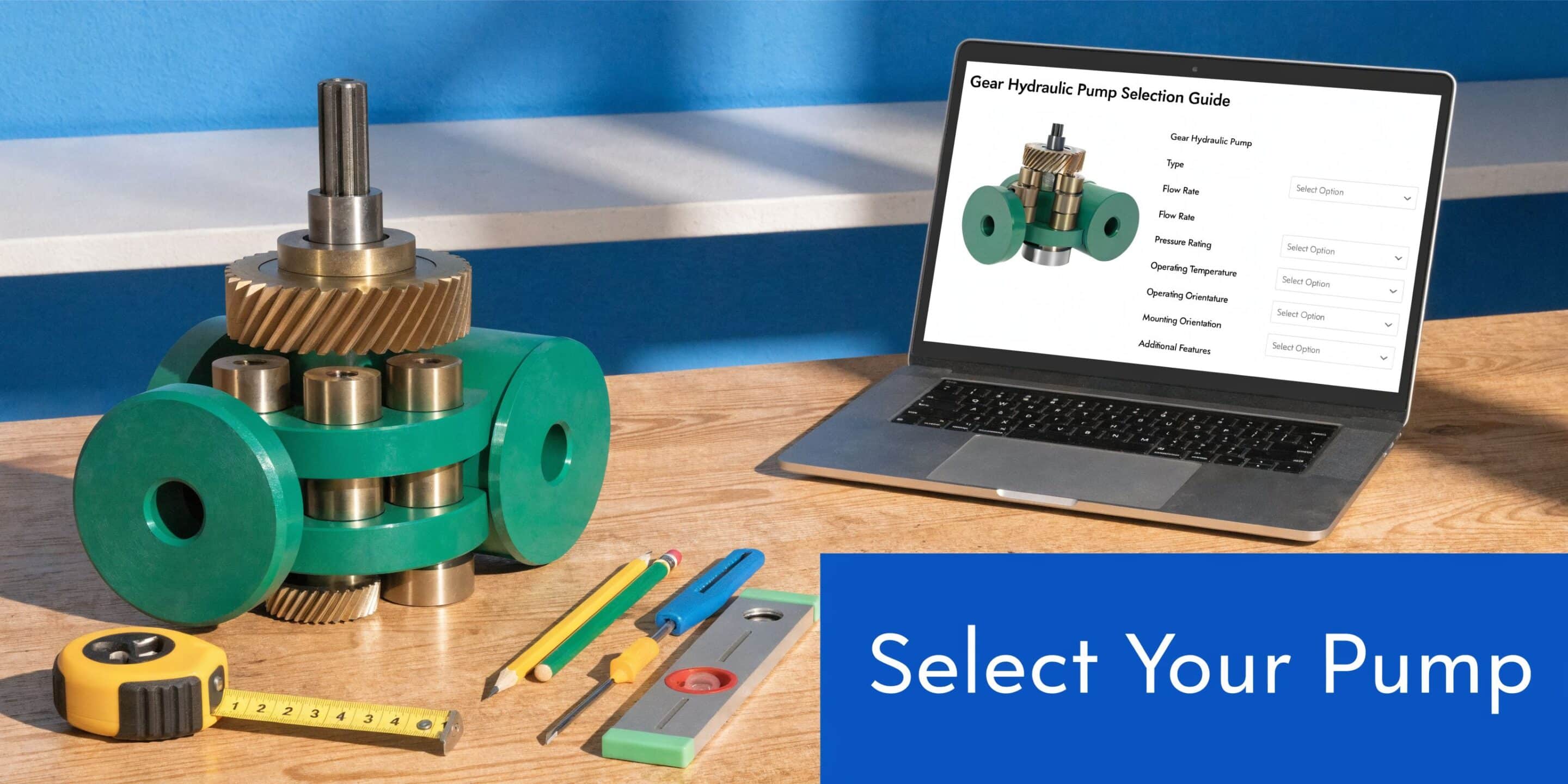
Start with four inputs
Before choosing a pump model, pin down these points:
-
Required flow
Usually expressed in L/min. This determines actuator speed. -
Operating pressure
Usually in bar. This determines whether the pump and drive arrangement are suitable for the load. -
Available drive speed
Motor speed, engine-driven speed, or PTO speed. A fixed displacement pump lives and dies by rpm. -
Duty pattern
Intermittent light work is very different from sustained industrial running.
The basic sizing logic
For a fixed displacement gear hydraulic pump, the first pass is straightforward. Flow comes from displacement multiplied by speed, then adjusted for real efficiency.
In practical terms:
Required displacement ≈ required flow ÷ drive speed
You then refine the choice against realistic operating conditions, expected losses, pressure rating, and inlet quality.
A worked approach
Take a common mobile example. A front-loader function needs a certain lifting speed, and the machine has a fixed drive speed available to the pump. If the selected displacement is too small, the loader will feel slow. If it is too large, the drive may struggle, the system may run hot, or the rest of the circuit may need redesign.
That is why experienced engineers do not buy on body size alone. They check:
- Can the prime mover sustain the pump at working rpm
- Is continuous pressure within the pump’s proper duty range
- Will the suction arrangement support the flow
- Does the mounting suit the machine without side load or alignment compromise
A compact industrial unit or mobile build often ends up in the Group 1 to Group 3 range, but that is only after the flow and fit are confirmed.
Selection checks that stop expensive mistakes
Match the pump to the drive
A pump can be correct hydraulically and still wrong mechanically. Electric motor-driven systems need coupling and bellhousing geometry that protects alignment. Engine and PTO-driven systems need the same level of care, even if the machine looks more tolerant.
Think about the fluid and temperature
Cold starts, outdoor storage, and long summer duty cycles change how the pump behaves. Viscosity on a winter morning can make inlet conditions harder than they appear on a bench test. A pump that survives in a clean indoor unit may struggle in a mobile machine with poor suction line practice.
Confirm whether fixed flow is suitable
Gear pumps are excellent for many duties, but they are fixed displacement devices. If the application needs frequent flow variation or high-end efficiency over a broad load range, another pump type may merit consideration.
For systems built around compact or bespoke hydraulic packages, the wider power unit layout matters as much as the pump itself. This overview of a hydraulic power unit is useful when the pump is only one part of the decision.
A short visual walkthrough can also help when comparing options and build considerations:
Where stocked pump ranges help
For replacement and new-build work, using stocked Groups 0 to 3 from brands such as Vivoil and OMT shortens the path from specification to installation because the available mounting and configuration options are already familiar to many engineers. MA Hydraulics Ltd supplies these ranges and also assembles bespoke power packs up to 11 kW, which is useful when the pump choice is tied to the whole unit rather than a standalone replacement.
Selection rule that holds up well: Pick the pump for the actual duty cycle and physical installation. Do not pick it only because the old one “looked about right”.
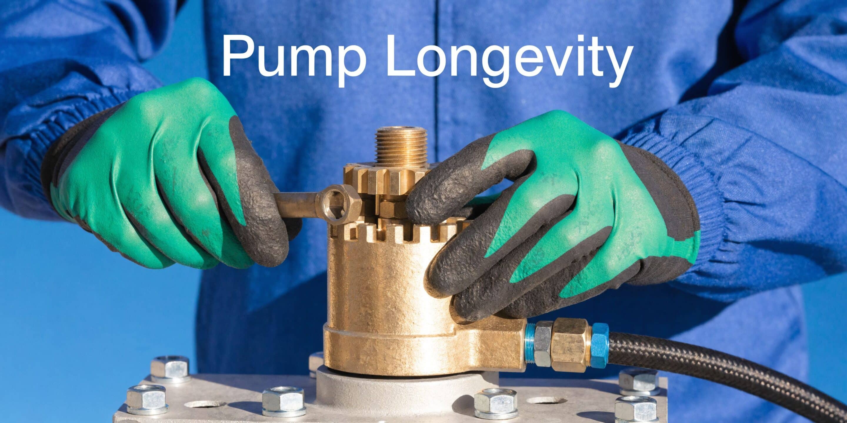
Installation and Maintenance for a Long Service Life
A new gear pump fitted on Friday can be back on the bench by Monday if the suction line is restrictive, the coupling is forcing the shaft off centre, or debris from a hose change has been left in the circuit. In UK mobile plant and industrial units alike, gear pumps usually fail early for installation and system reasons, not because the gear set was weak.
That matters with stocked replacement pumps from Vivoil and OMT as much as with pumps built into a bespoke power pack. The unit may bolt straight on, but service life still depends on how well the surrounding system has been prepared.
Installation errors that do damage quickly
Early damage usually starts at the inlet or the drive.
A pump installed with the wrong rotation may not prime properly and can score internal parts within minutes. Dirty pipework causes a different kind of failure. Fine debris from new hoses, tank fabrication, thread sealant, or reused fittings gets carried straight into the pump and starts wearing side plates and bearings before the machine has done any useful work.
Poor suction layout is another regular cause of trouble. Long inlet lines, undersized hose, tight bends, clogged strainers, and weak joints all reduce inlet conditions. The result is noise, aeration, cavitation, and erratic performance that operators often mistake for a faulty replacement pump.
Misalignment is just as expensive. If the pump has to be pulled into place with the mounting bolts, the shaft seal and bearings will usually show the cost first.
What proper alignment looks like
A correctly aligned pump sits naturally on the mounting face and couples to the drive without side load. The coupling transmits torque. It should not be compensating for a poor bracket, paint build-up, burrs, or incorrect shaft engagement.
In workshop practice, four checks prevent a lot of repeat failures:
- Clean the mounting face and register properly
- Check shaft engagement so it is neither shallow nor bottomed out
- Confirm the coupling is suitable for the duty and fitted without preload
- Turn the assembly by hand, where safe, before first start
If a replacement pump keeps leaking at the shaft seal, inspect alignment and drive condition before blaming the seal itself. Repeated seal failures usually point to side load, pressure spikes, or housing distortion. Where the cause is unclear, a proper hydraulic pump repair assessment often saves fitting another pump into the same fault.
Maintenance habits that extend pump life
Good maintenance for a gear pump is straightforward, but it has to be consistent.
-
Keep the oil clean
Contamination wears gear tips, bushes, and side plates steadily. If a pump has failed internally, flush the circuit before fitting the next one. -
Listen for a change in sound
A harsher or more metallic note often points to inlet restriction, air ingress, or internal wear before pressure and flow fall away badly. -
Inspect external leaks early
Oil around the shaft seal or body joints can indicate more than age. Check case pressure, mounting stress, and pressure peaks in the circuit. -
Watch operating temperature
Heat usually has a cause. Common ones are prolonged relief valve operation, viscosity that is wrong for the duty, internal leakage, or inadequate cooling. -
Check the basics after commissioning
Recheck fasteners, pipe supports, hose routing, and oil level after the first period of operation. Small installation faults often show up once the unit has warmed through.
What does not work
Running a noisy pump and hoping it beds in rarely ends well. Swapping the pump without cleaning the tank and lines usually creates the same failure twice. Changing seals alone also wastes time if the problem is alignment, inlet starvation, or contamination.
Gear pumps are tolerant machines, which is one reason they suit so many UK agricultural, mobile, and industrial duties. They still need clean oil, a sound inlet path, and a drive arrangement that does not load the shaft sideways. Get those points right and even a simple Group 1, 2, or 3 pump will usually give long, predictable service.
Troubleshooting Common Gear Pump Problems
A telehandler comes in with sluggish boom lift, a harsher pump note than last week, and oil temperature climbing by mid-shift. In practice, that combination rarely points to one fault in isolation. It usually means the pump, inlet side, relief setting, and oil condition all need checking together before anyone orders parts.
Gear pumps are simple machines, but fault-finding is not always simple. The same symptom can come from the pump itself, the drive, or the wider circuit. On UK mobile and industrial equipment, the repeat failures we see most often start with contaminated oil, suction-side problems, wrong rotation after replacement, or a new pump fitted to a system that still has the original root cause.
Quick fault guide
| Symptom | Likely causes | Action |
|---|---|---|
| No flow or very low flow | Wrong rotation, blocked suction path, severe internal wear, pump not being driven correctly | Confirm rotation, inspect inlet line and filter, verify coupling or drive engagement, test pump condition |
| Excessive noise | Cavitation from fluid starvation, aeration from air ingress, misalignment, worn internals | Check oil level, suction seals and hose condition, inlet restrictions, alignment, and wear signs |
| Slow actuator movement | Pump displacement too small, low drive speed, internal leakage, relief valve passing | Verify actual rpm, confirm selected displacement, test pressure and relief behaviour |
| Overheating | Pump working across relief too often, efficiency loss, poor reservoir or cooling arrangement, wrong viscosity | Check circuit duty, relief settings, oil condition, and cooling provision |
| External leakage | Damaged shaft seal, overpressure, poor alignment, damaged port seals | Inspect seal area, check mounting and coupling, confirm system pressure is within rating |
| Intermittent performance | Air ingress, unstable prime, contamination, variable drive speed | Check suction integrity, oil condition, and consistency of prime mover speed |
How to separate similar symptoms
Cavitation and aeration need different fixes
Both make a gear pump noisy. The cause is different, and so is the remedy.
Cavitation starts with poor inlet conditions. The pump is trying to fill the tooth spaces faster than oil can reach them, so vapour cavities form and collapse. That gives a sharper, harsher sound and will mark internal surfaces if it continues. Common causes are undersized suction hose, blocked strainers, cold oil, or a tank outlet that is too restrictive for the duty.
Aeration means air is getting into the oil. The note is often more irregular, and the oil in the tank may look milky or foamy. Check hose clips, pipe unions, shaft seal condition, and any suction hose that has gone hard or cracked with age. On older plant, a tiny air leak on the inlet side can cause far more trouble than a visible pressure-side seep.
Low flow does not confirm pump failure
A fixed displacement pump can only deliver what its displacement and input speed allow. If the prime mover is running below expected rpm, or the relief valve is passing early, flow at the actuator will look poor even though the pump is serviceable.
Pressure and flow need reading together. A pump with worn internals may still build some pressure, but struggle to hold performance as oil warms up. A healthy pump feeding a relief valve stuck partly open can produce a very similar complaint from the operator's seat.
Heat usually has a system cause
If the tank is running hot, look for where energy is being lost. Relief valve operation, internal leakage across worn components, and oil viscosity outside the duty range are common causes. On compact power packs and older industrial units, limited reservoir volume makes the problem show up faster.
This matters when selecting a replacement. A standard Group 2 or Group 3 unit from brands such as Vivoil or OMT may be the correct physical fit, but if the original application has poor cooling or chronic overpressure, the replacement will live the same short life.
External leaks need context
A wet shaft seal does not automatically mean the seal itself was the first failure. Misalignment, shaft loading from a poor coupling setup, pressure spikes, or blocked drain paths elsewhere in the system can all force oil past the seal. Check the drive arrangement and pressure history before condemning the pump on appearance alone.
For units already showing wear or uncertain damage, a proper hydraulic pump repair assessment can be more useful than stripping and guessing. That is often the sensible route where the machine has had contamination, repeated seal failure, or an application-specific mounting that needs closer review.
Workshop rule: Test the circuit around the pump, not just the pump on its own. Root cause first. Replacement second.
In the workshop, the best results come from a short fault-finding routine. Confirm rotation. Check inlet vacuum or restriction. Compare cold and hot performance. Inspect the oil and filter debris. Then decide whether the issue is the pump, a valve problem, or the wider package. That approach saves time, and on bespoke power pack work it often shows that the pump is only one part of the problem.
Your Partner for UK Hydraulic Pump Solutions
A gear hydraulic pump is one of the most practical components in fluid power. It delivers fixed flow predictably, fits a wide range of mobile and industrial duties, and rewards correct installation with long service life. That combination is why it remains such a common choice across UK agriculture, plant, materials handling, and manufacturing.
The important part is not just buying a pump that bolts on. It is matching the right displacement, group, rotation, pressure capability, and drive arrangement to the actual duty. That is where many avoidable failures begin or end.
For replacement work, it helps to have access to standard Groups 0 to 3, including unidirectional and reversible options, plus related parts such as couplings, bellhousings, valves, and filtration. For new equipment or upgrades, the pump often needs to be considered alongside the full hydraulic package, especially when the system is built around a compact or bespoke power unit. Here, practical support matters. A supplier who understands mobile and industrial applications can help identify whether the issue is the pump itself, the mounting, the inlet arrangement, or the wider circuit. That saves time and usually saves repeat failures.
If you are specifying a new gear hydraulic pump, replacing a worn unit, or working through a recurring hydraulic fault, clear application data always helps. Pump model, displacement, direction of rotation, operating pressure, drive speed, mounting style, and a brief description of the machine duty will usually get the process moving quickly.
If you need help with a gear hydraulic pump, replacement parts, or a complete hydraulic solution, contact MA Hydraulics Ltd. Phone 01724 279508 today, or send us a message at https://www.mahydraulics.co.uk/contact-us/
