
You’re usually not reading about a motor pump hydraulic system out of idle curiosity. More often, you’re standing at one of two points.
Either you’re specifying a new machine and trying to make a compact package deliver serious force without creating a maintenance headache later. Or you’re dealing with a tired unit in service, where the replacement on paper looks simple until shaft sizes, porting, duty cycle, mounting, contamination history, and compliance details start to complicate the job.
Such is the state of hydraulic systems in UK industry. The pump, motor, coupling, reservoir, valve block, and filtration don’t fail or succeed as isolated parts. They succeed as an assembly. Good engineering happens when the whole unit is sized properly, mounted properly, and maintained like a working asset rather than a catalogue item.
The Heart of Modern Machinery An Introduction to Hydraulic Motor Pumps
A practical example makes the point quickly. An OEM building a compact piece of mobile plant wants high force in a small footprint. A factory maintenance team wants to upgrade a conveyor, press, clamp, or lift table without redesigning the whole machine. In both cases, the same question appears early. How do you convert available electrical or mechanical input into controlled hydraulic output that’s strong, compact, and serviceable?
That’s where the motor-pump assembly earns its place. The motor provides the drive. The pump converts that rotational input into hydraulic flow. The rest of the system turns that flow and pressure into useful motion.
Hydraulics remain hard to beat where you need power density, controlled movement, and flexibility in layout. You can place actuators away from the prime mover, manage overloads sensibly, and package substantial force into machines that would become bulky or mechanically awkward with a purely mechanical drive.
Where these systems earn their keep
In UK service work, motor pump hydraulic assemblies commonly sit inside:
- Agricultural machinery where PTO speed, shock loading, and outdoor contamination all affect component choice
- Materials handling equipment where repeatable motion matters more than theoretical peak output
- Manufacturing systems where duty cycle, heat rejection, and service access decide whether a design is pleasant or miserable to maintain
- Building services and lifting applications where controlled movement and compact installation matter, and resources such as A Building Owner's Guide to Hydraulic Elevators help frame the broader hydraulic principles from an end-user perspective
A hydraulic system that looks excellent on a drawing can still be poor in service if no one has thought about alignment, suction conditions, oil cleanliness, and access for filter changes.
The difference between a reliable unit and a troublesome one usually isn’t one dramatic error. It’s a string of small decisions made too quickly. Pump type. Motor speed. Reservoir layout. Coupling fit. Return filtration. Hose routing. Pressure setting. None of them are glamorous. All of them matter.
Choosing Your Power Source Hydraulic Pump Types Explained
A pump choice that looks fine on a datasheet can turn into a poor machine once it is bolted into a chassis, coupled to a PTO, and handed to a maintenance team on a wet yard in Lincolnshire or a factory floor in the Midlands. Pump selection is not only about pressure and flow. It is also about dirt tolerance, cold starts, noise, replacement lead time, shaft loading, and whether the unit can still be supported five years from now.
At MA Hydraulics, we usually start with the duty and the service reality. A clean indoor power unit with stable motor speed gives far more freedom than a mobile machine that sees shock loading, rushed servicing, and oil of uncertain condition. The right pump is the one that survives the job, not the one that wins the catalogue comparison.
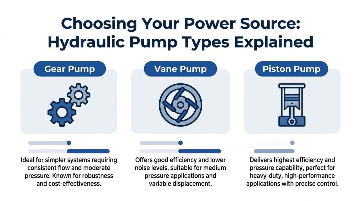
Gear pumps
Gear pumps earn their place because they are simple, widely understood, and generally forgiving in service. They suit many fixed-displacement circuits where the priority is dependable output rather than fine control.
For agricultural attachments, compact power packs, tipping gear, and general plant, a gear pump is often the most sensible starting point. It is usually easier to source quickly in the UK, easier to replace during breakdown work, and less sensitive to marginal operating conditions than more complex designs. Where a machine needs straightforward performance and predictable maintenance, a gear hydraulic pump for fixed-displacement systems is often the right fit.
There are limits. Gear pumps tend to get noisy when pushed hard, and they are not the first choice where low-ripple flow, tight control, or high operating pressure drives the design.
Vane pumps
Vane pumps sit in the middle of the range. They are often chosen where smoother running and lower noise matter more than absolute ruggedness.
In a clean industrial environment, vane technology can make sense for machine tools, production equipment, and other installations where operators work close to the power unit and notice every change in sound or response. The trade-off is maintenance discipline. Poor filtration, varnish, or inconsistent oil quality will show up faster in a vane pump than in a basic gear unit.
That is why vane pumps are rarely my first recommendation for exposed mobile equipment or neglected service conditions. They can perform well, but only if the rest of the system is given the same level of care.
Piston pumps
Piston pumps belong in applications that need higher pressure capability, tighter control, variable displacement, or better power density. They are common on advanced mobile plant, test systems, presses, and compact packages where space is limited but output cannot be compromised.
The benefit is clear. Higher pressure capability can reduce actuator size, hose size, and overall package volume. In the right system, that can justify the extra cost. Analysts at Design World outline the typical performance advantages and selection factors in this hydraulic pump technology guide.
The cost of that performance is sensitivity. Piston pumps ask more of the installation and the maintenance regime. Poor suction conditions, dirty oil, coupling misalignment, and heat will usually be punished sooner and more expensively than with a gear pump.
Practical rule: Choose a piston pump only when the machine benefits clearly from the extra pressure capability, controllability, or package efficiency.
Speed range matters more than many specifications suggest
Pump behaviour changes across the speed band. A unit that runs well at one operating point may feel lazy, noisy, or harsh somewhere else.
This matters in UK mobile equipment because prime mover speed is often less stable than the design assumptions. PTO-driven systems, diesel engine drives, and machines that spend time idling before full demand all create conditions where pump efficiency, filling, and noise shift across the day. If the selected pump only behaves properly in a narrow speed window, the machine will expose that weakness quickly.
That is one reason experienced OEM teams do not choose from pressure rating alone. They check starting torque, minimum speed behaviour, suction pipe losses, and what happens in winter starts with cold oil. MRO teams care about the same points for a different reason. Those are often the details behind repeat failures.
A selection guide that adds service reality
The usual pump-type summary is useful, but it becomes more useful when you add procurement and maintenance consequences.
| Pump type | Best fit | Main trade-off | Typical UK sourcing reality | Maintenance implication |
|---|---|---|---|---|
| Gear pump | General mobile plant, agriculture, simple industrial circuits | More noise and less refined control | Usually the easiest to source from stock or cross-reference | Usually the easiest for breakdown replacement and routine service |
| Vane pump | Quieter industrial equipment in controlled environments | Less tolerant of contamination and neglected oil | Availability can be narrower, especially for older units | Cleanliness and oil condition matter more to service life |
| Piston pump | High-pressure systems, variable-displacement circuits, compact high-output machinery | Higher cost, higher sensitivity, more demanding integration | Often requires closer matching by code, control type, and mounting detail | Installation quality and contamination control strongly affect lifespan |
For UK OEMs, that sourcing point matters. A design built around a specialist pump can be perfectly sound technically and still create downtime if replacement units or seal kits are difficult to obtain during service. For MRO work, the opposite problem appears just as often. A readily available substitute gets fitted, but the control arrangement, drain requirement, or shaft loading does not match the original unit, and the machine never performs properly again.
Pick from the job backwards
A sound decision starts with a few blunt questions.
- What must the actuator do in service, not only on paper?
- How clean will the oil stay between maintenance visits?
- Will the machine live indoors, on a farm, on a quarry edge, or in a washdown area?
- Is low noise a preference, or a requirement?
- Does the customer need the fastest possible replacement from UK stock, or the smallest and most power-dense package?
- Can the maintenance team support the pump type you are specifying?
Those answers usually narrow the field quickly. Gear pumps suit many honest working circuits. Vane pumps suit cleaner and quieter duties. Piston pumps suit demanding systems where the rest of the design, and the maintenance regime, are good enough to support them.
That is the gap many selection guides miss. Pump choice is not finished when the numbers work. It is finished when the unit can be mounted properly, supplied reliably, serviced realistically, and kept alive in the conditions the machine will face.
Sizing and Performance Calculations for Optimal Efficiency
A lot of hydraulic trouble starts with bad arithmetic disguised as confidence. Someone picks a pump because the mounting fits, or because the old one “looked about right”, or because the machine used to work well enough. That isn’t sizing. That’s guesswork with expensive consequences.

The core calculations are not complicated. The discipline is in using them early enough, and then checking whether the machine itself can support the result.
Start with pressure and flow
For UK hydraulic systems, the standard power relationship is Power (kW) = (P × Q) ÷ 600, where P is pressure in bar and Q is flow in L/min, as set out in this hydraulic formulas guide.
That equation gives you a fast way to check whether your electric motor, engine drive, or compact power pack is in the right territory.
If you already know the actuator’s required force and speed, you can work backwards into pressure and flow. Once you know the flow target, you can relate it to pump displacement and speed using Q = (D × N) ÷ 1000, where D is displacement and N is speed.
A practical sizing method
Use this order. It avoids a lot of redesign later.
- Define the machine duty. Decide what motion you need, how often it repeats, and whether the load is constant or variable.
- Set the working pressure. Don’t set this at relief-valve maximum by habit. Set it around the load requirement with a sensible margin.
- Calculate required flow. Actuator speed drives flow demand.
- Select pump displacement from available drive speed. If the machine uses PTO or a motor with a known speed, displacement must suit that actual operating speed.
- Check power demand. If the calculated kW is beyond what the prime mover or power pack can sustain, the design must change.
If your numbers only work at ideal speed, ideal oil viscosity, and ideal cleanliness, they don’t work.
Why theoretical numbers still need correction
Hydraulic design on paper gives you theoretical output. The machine gives you actual output.
In the UK hydraulic industry, high-performance piston pumps can achieve volumetric efficiencies of up to 94% at 350 bar and 40 cSt fluid viscosity, as shown in this volumetric efficiency reference. The example is simple and useful. A pump with a theoretical output of 100 L/min that delivers 94 L/min at those conditions is operating at 94% volumetric efficiency.
That matters because engineers often size from nominal flow and forget leakage effects under pressure. The result is a machine that looks fine on the drawing and underperforms in service.
The same source notes that pairing such a pump with a piston motor gives an overall hydraulic drive efficiency of 85%. That’s a strong result, but it also reminds you that total system output is always lower than the neat arithmetic of isolated components.
Keep viscosity in view
Volumetric efficiency is closely tied to internal leakage. Leakage rises with pressure and gets worse as viscosity drops. In practical terms, oil that’s too thin for the operating condition costs you flow, heat, and control quality.
That’s one reason a machine that behaves perfectly when cold can become sluggish or noisy once the oil temperature climbs. The calculations are still useful. They just need to be read as the start of engineering judgement, not the end of it.
For a closer look at pressure relationships in hydraulic systems, this guide on how pressure is calculated is a useful reference point.
A visual walk-through can also help when you’re checking the maths against actual component behaviour.
System Integration Mounting Coupling and Power Packs
A correctly chosen pump can still fail early if the mounting arrangement is poor. Integration work looks mundane until you’ve seen enough broken couplings, wiped seals, noisy bellhousings, and cracked brackets. Then you realise most “bad components” were never bad components at all.
Alignment is mechanical, not optional
When coupling an electric motor to a hydraulic pump, the bellhousing and coupling do more than join two shafts. They hold concentricity, control alignment, and reduce the side-loading that destroys bearings and shaft seals.
Flexible couplings help, but they don’t excuse poor assembly. If the bellhousing face isn’t clean, the spigot is wrong, the coupling insert is mismatched, or the shafts are forced together, the unit starts life under stress.
Common fitting mistakes include:
- Driving the coupling halves together by force. If it only fits with persuasion, something is wrong with the shaft, key, or coupling selection.
- Ignoring shaft engagement. Too little engagement risks fretting and shock damage. Too much can preload the assembly.
- Treating flexible elements as a cure-all. A spider coupling will tolerate small errors. It won’t rescue a badly aligned build.
Power pack layout decides service life
A proper hydraulic power pack is more than a motor and pump bolted to a tank. Reservoir volume, suction line arrangement, return filtration, breather quality, valve placement, and access for service all affect system life.
The smallest compact units still need proper thought around:
- Reservoir behaviour so the oil can de-aerate and reject heat
- Filtration placement so contamination control supports the pump rather than starving it
- Relief and control valves sized for the circuit, not added as afterthoughts
- Physical access so maintenance teams can change filters, inspect hoses, and test pressures without dismantling half the unit
For packaged assemblies, a purpose-built hydraulic power unit gives engineers a clearer route than trying to improvise around loose parts. That matters most when space is tight or the machine builder wants a repeatable specification across multiple units.
Good integration work is quiet. The machine starts cleanly, runs smoothly, and doesn’t ask for attention every few weeks.
What tends to work in the field
In UK mobile and industrial service, compact motor-pump sets do best when the installer respects three things. Shaft alignment, suction conditions, and maintainability.
If any one of those is weak, the rest of the system spends its life compensating. Operators hear noise first. Maintenance sees leaks next. Procurement gets the parts request after that.
Troubleshooting Common Hydraulic Motor Pump Failures
Most fault-finding goes wrong because people jump to the failed part before understanding the failure pattern. A noisy pump gets condemned. A leaking seal gets replaced. A sluggish actuator gets blamed on “worn hydraulics”. Then the same fault returns because the root cause was never removed.

The better approach is to read the symptoms in order. Noise, temperature, leakage, slow movement, erratic movement, pressure loss, and contamination signs each tell part of the story.
Misalignment and mechanical stress
Misalignment is more damaging than many teams realise. In hydraulic motor-pump systems, it contributes to 50% of breakdowns and can increase energy consumption by up to 15%, according to this alignment guidance.
That shows up as:
- Seal leakage at the pump shaft
- Coupling wear or failed inserts
- Bearing noise that grows under load
- Heat build-up from mechanical drag
- Repeat failures after what looked like a successful part replacement
If you replace the pump without checking bellhousing fit, shaft alignment, base rigidity, and coupling condition, you haven’t repaired the cause.
Cavitation and aeration
These faults are often confused because both make noise and both damage performance. They aren’t the same.
Cavitation usually points to poor inlet conditions. Restricted suction, cold oil, undersized inlet plumbing, blocked strainers, or excessive speed can all trigger it. The pump sounds harsh. Over time you may see surface damage or loss of output quality.
Aeration means air is entering the fluid. The machine may sound rough or erratic, but the feel of the system can also become spongy. Look for loose suction fittings, poor hose condition, leaking shaft seals on the inlet side, or reservoir issues that allow air entrainment.
Contamination and wear
Contamination remains one of the most common reasons a motor pump hydraulic system deteriorates early. The signs aren’t always dramatic at first.
Watch for:
- Sticking valves that come and go
- Rapid filter loading
- Scored components when the unit is stripped
- Darkened or degraded oil
- Performance that drifts over time rather than failing suddenly
Fine contamination often creates a broad pattern of minor issues before one major component finally fails. That’s why clean replacement parts don’t stay healthy in dirty systems.
Strip enough failed pumps and you start seeing the same truth. Many failures begin upstream, long before the damaged component is removed from the machine.
Overheating and falling performance
Heat is rarely the first problem. It’s often the visible symptom of another one.
A unit runs hot when energy is being wasted. That can come from internal leakage, relief-valve bypassing, mechanical drag, oil that’s too thin at operating temperature, or poor reservoir and cooling design. If the machine gets hotter as performance falls away, suspect leakage and efficiency loss before you blame the thermometer.
A useful fault-finding sequence
When a unit comes in with uncertain history, this order saves time:
- Listen first. Noise character gives clues before tools come out.
- Inspect the coupling and shaft area. Leakage, rubber debris, and dust patterns often reveal misalignment.
- Check oil level and condition. Don’t skip the basics.
- Look at the suction side. Restrictions and air ingress hide there.
- Measure pressure under known conditions. Not just relief setting.
- Check operating temperature trend. Heat without context means little.
- Only then condemn major components.
That sequence doesn’t make fault-finding slower. It stops repeat failures.
Proactive Maintenance for Long-Term System Health
Reactive maintenance always looks cheaper right up to the point where the machine stops at the wrong time. Then the true cost appears. Lost production, contaminated oil, damaged couplings, emergency labour, and rushed parts decisions all cost more than routine care ever did.
A strong maintenance routine doesn’t need to be complicated. It needs to be consistent and tied to failure prevention.
What a useful maintenance rhythm looks like
Daily and weekly work should stay simple enough that operators and maintenance staff do it.
- Daily checks should cover visible leaks, hose abrasion, reservoir level, and any change in sound during start-up.
- Weekly checks should include coupling condition, mounting bolt security, filter condition indicators where fitted, and general cleanliness around breathers and filler points.
- Monthly attention should focus on oil condition, operating temperature trends, and whether actuator speed or machine response has drifted.
- Periodic deeper checks should include filter replacement, line inspection, and fluid analysis where the asset justifies it.
Why fluid discipline pays back
Hydraulic oil isn’t just a power medium. It lubricates, carries heat, and reports on system condition if you pay attention to it.
Clean oil with the correct viscosity supports predictable pump behaviour. Dirty or degraded oil shortens the life of everything downstream. The maintenance teams that get the best service life usually treat oil and filtration as first-order engineering controls, not consumables to be delayed.
Maintenance isn’t separate from reliability. It’s the method that creates reliability.
The practical mindset shift
The most useful change for many sites is simple. Stop asking, “Has it failed yet?” Start asking, “What would this unit look and sound like if it were starting to fail?”
That mindset catches:
- loosening couplings before they chew shafts,
- air ingress before it damages the pump,
- overheating before seals harden,
- contamination before it reaches valves and motors.
Preventive work rarely feels dramatic. That’s the point. Good maintenance removes drama from hydraulics.
Specification and Procurement A Guide for UK Engineers
Procurement trouble usually starts earlier than the purchase order. It starts with a thin specification.
If you ask suppliers for “a replacement hydraulic pump and motor set”, you’ll get questions back or, worse, you’ll get something that technically fits one detail and misses three others. Good procurement begins with a technical brief that gives enough information to quote the correct assembly first time.
What the specification must include
A usable hydraulic specification should state:
- Working pressure and maximum pressure
- Required flow
- Duty cycle and operating pattern
- Prime mover details, including speed
- Mounting arrangement, shaft data, and coupling constraints
- Port types and sizes
- Fluid type and expected operating conditions
- Application details, including whether the machine is mobile, industrial, indoor, outdoor, clean, or dirty
Without those, part matching becomes guesswork.
Buy support, not just hardware
Two pumps with similar catalogue descriptions can produce very different ownership experiences depending on stock availability, application advice, and whether the supplier understands assemblies rather than single parts.
That matters most when you need:
- a pump and motor matched properly,
- a bellhousing and coupling selected around real shaft dimensions,
- a compact power pack assembled to suit the machine,
- cross-reference support for older or hard-to-identify units.
In those cases, support on component matching is part of the product, even if it doesn’t appear on the invoice line.
Compliance matters more on retrofit work
A key challenge for UK agricultural MRO teams is sourcing retrofitted hydraulic motor pumps that comply with post-Brexit standards such as the Supply of Machinery (Safety) Regulations 2008, and non-compliance can lead to significant fines, making supplier understanding of UKCA and regulatory alignment important, as noted in this troubleshooting and compliance context.
That issue is easy to underestimate on retrofit jobs. The hydraulic function may be straightforward, but once you alter a machine assembly, documentation, marking, guarding, and safety responsibilities come into play.
One practical route for UK engineers is to source through a supplier that can support component matching and packaged assemblies, including bespoke power packs up to 11 kW. MA Hydraulics Ltd is one such UK option for that kind of work, particularly where the brief includes stocked components, assembly support, and application guidance rather than a single loose replacement part.
Conclusion Your Partner in Hydraulic Excellence
A dependable motor pump hydraulic system doesn’t come from one good component. It comes from a chain of good decisions. Choose the right pump technology for the duty. Size it from real pressure and flow needs. Mount it accurately. Protect it with proper filtration and oil management. Diagnose faults from evidence, not assumptions. Buy with the full machine and the compliance picture in mind.
That’s how systems stay efficient, serviceable, and predictable in real UK operating conditions.
For expert advice on your application, component matching, or bespoke assemblies, contact MA Hydraulics Ltd. Phone 01724 279508 today, or send us a message at https://www.mahydraulics.co.uk/contact-us/
