At its core, a hydraulic circuit symbol is a shorthand, a universal visual language used by engineers and technicians worldwide. These graphical icons represent a component’s function within a circuit, not what it physically looks like. Think of them as the alphabet of fluid power.
They show us how things like pumps, valves, and actuators are plumbed together and how they interact to make the system work.
Decoding the Language of Hydraulic Systems
Getting to grips with hydraulic circuit symbols is absolutely fundamental to working with fluid power systems. These diagrams are the blueprints for everything from massive industrial power packs to the intricate systems in mobile plant equipment. They are essential for design, assembly, and, crucially, for troubleshooting when things go wrong.
Without being able to read this visual language, trying to figure out how a system works is guesswork at best. That can lead to expensive mistakes, prolonged downtime, and even serious safety hazards. Being fluent in these symbols means you can accurately trace the path of the hydraulic fluid, understand what each component is supposed to be doing, and pinpoint problems with confidence. It’s the key to making sure every part of the system works in harmony.
The Importance of Standardisation
The standardisation of these symbols, mainly under ISO 1219-1, is a huge deal for the UK’s engineering and manufacturing industries. It creates a universal system, meaning a schematic drawn up by an engineer in Scunthorpe can be perfectly understood by a technician on the other side of the world. This level of consistency gets rid of any ambiguity, which is vital when you’re dealing with high-pressure systems where a misunderstanding can be catastrophic.
The main benefits of having one standard system are pretty clear:
- Clarity in Communication: It puts everyone on the same page. Engineers, maintenance crews, and suppliers all speak the same, unambiguous language.
- Enhanced Safety: When you can correctly identify a pressure relief valve or an emergency stop on a diagram, you’re in a much better position to operate and maintain the machinery safely.
- Improved Efficiency: Technicians can find faults faster, identify the right replacement parts, and get the machine back up and running with minimal downtime.
Learning to read these diagrams isn’t just about recognising lines and shapes. You’re interpreting a detailed plan that dictates the power, control, and ultimate performance of complex machinery. This guide is your comprehensive reference to help you become fluent in the language of hydraulics.
For expert advice on picking the right components for your hydraulic circuit, give us a call on 01724 279508 today, or send us a message.
2. Foundational Principles of Hydraulic Symbolism
Before we jump into the symbols for every single pump, valve, and motor, it’s worth taking a moment to understand the “grammar” of hydraulic schematics. Think of it like learning the alphabet before you try to read a book. Every complex circuit diagram is built from a small, consistent set of basic shapes and lines, each with a specific meaning defined by the ISO 1219-1 standard.
Get these core building blocks down, and you’ll find you can start to make sense of even the most intimidating-looking circuits. It’s this foundational knowledge that lets you see how all the individual components work together as a complete system.
Core Shapes and What They Represent
At the very heart of hydraulic diagrams are a few simple geometric shapes. These are your starting point for becoming fluent in reading schematics.
-
Circles: A circle almost always signifies a device that converts energy. It’s the base symbol for a hydraulic pump (which turns mechanical energy into hydraulic power) or a motor (which does the complete opposite).
-
Squares: A square or a rectangle is the universal symbol for a directional control valve. These are the components that direct, stop, or start the flow of fluid. When you see several squares joined together, it tells you the valve has multiple switching positions.
-
Diamonds: The diamond shape is reserved for fluid conditioning components. This category covers everything that maintains the health of the hydraulic fluid, like filters, coolers, and heaters.
A classic mistake for anyone new to hydraulics is trying to match the symbol to what the component physically looks like. You have to remember that symbols represent the function of a part, not its size, shape, or who made it. This focus on function is precisely what makes hydraulic schematics a universal language across the industry.
To help you get started, here is a quick overview of the most fundamental elements you’ll encounter in any hydraulic schematic.
Quick Reference for Basic Hydraulic Symbol Elements
This table summarises the essential shapes and lines that form the foundation of all hydraulic circuit diagrams, as defined by ISO 1219-1.
| Symbol Element | Shape or Line Type | Represents |
|---|---|---|
| Circle | An energy conversion device, such as a pump or motor. | |
| Square | A directional control valve or a single position of a valve. | |
| Diamond | A fluid conditioning component, like a filter, cooler, or heater. | |
| Solid Line | A main working line or flow path for hydraulic power. | |
| Dashed Line | A pilot line, used for control signals. | |
| Dotted Line | A drain or bleed line, returning fluid to the tank. | |
| Connection Dot | Indicates that intersecting lines are connected. | |
| No Connection | Indicates that lines cross over each other without connecting. |
Mastering these few elements is the first major step towards being able to confidently read and interpret any hydraulic circuit you come across.
Understanding Lines and Connections
If the components are the organs of the system, the lines are the veins and arteries, showing exactly how fluid gets from one place to another. The type of line used tells you its specific job.
Solid Lines: These are your main working lines. They show the primary flow paths where the real work is being done and hydraulic power is being transmitted.
Dashed Lines: A dashed line represents a pilot line. These lines carry a much smaller volume of fluid, which is used to control another component, like signalling a larger valve to shift its position.
Dotted Lines: You’ll typically see these used for drain lines, which carry low-pressure fluid (often from leaks or case drains) back to the main reservoir.
Don’t forget the arrows on these lines—they’re critical for showing the direction of flow. Also, pay close attention to where lines cross. A small dot at the intersection means the lines are connected (think of a ‘T’ junction in a pipe). If they just cross over without a dot, they are not connected and are simply passing over one another. Getting that distinction right is key to avoiding serious misinterpretations of the circuit’s plumbing.
Symbols for Pumps and Motors
Pumps and motors are really the heart and muscle of any hydraulic system. One creates the power, and the other does the work. Pumps are there to convert mechanical energy into hydraulic energy in the form of flow, while motors do the exact opposite, turning that hydraulic energy back into mechanical rotation. Getting to grips with their specific symbols is the first, most crucial step in tracing a circuit or diagnosing a fault.
The starting point for both pump and motor symbols is a simple circle. The real giveaway, the detail that tells you what it actually does, is the small, solid triangle inside. Think of this triangle as an arrow showing the direction of energy. If the triangle points outwards from the centre, it’s a pump – it’s pushing fluid out and into the circuit. If it points inwards, it’s a motor, taking fluid in from the circuit to produce torque.
This simple diagram below shows the basic shapes for some core hydraulic components.
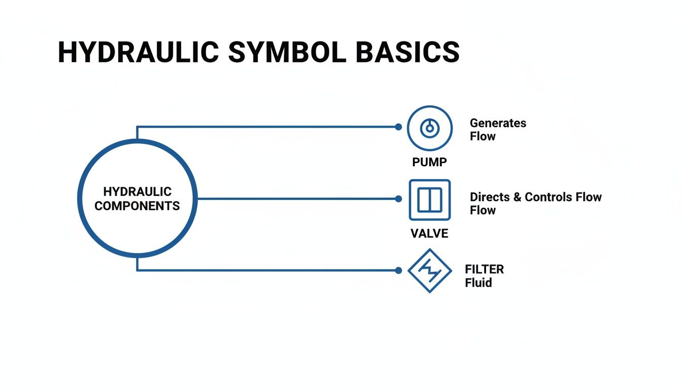
As you can see, a circle represents a pump, a square is used for a valve, and a diamond shape signifies a filter. These are the building blocks, the core “grammar” you need to read any hydraulic schematic.
Differentiating Pump and Motor Types
Of course, the symbols tell you far more than just whether it’s a pump or a motor. For any engineer on the job, the extra details are what really matter. The number of triangles and other small additions reveal critical information about how the component operates.
- Unidirectional vs. Bi-directional: A single triangle means the component is unidirectional – it only works in one direction. Two triangles, pointing in opposite directions, tell you it’s a bi-directional pump or motor, which can operate in both clockwise and anti-clockwise rotations. Many of the Vivoil gear pumps we stock, for instance, are available in both configurations.
- Fixed vs. Variable Displacement: A plain circle represents a fixed displacement pump or motor. This type moves a specific, unchangeable volume of fluid with every single revolution. However, if you see a diagonal arrow drawn right through the circle, that symbol now represents a variable displacement component. That arrow is your clue that its output flow (if it’s a pump) or its speed (if it’s a motor) can be adjusted, even if its input speed remains constant. You can explore a variety of manually operated options in our collection of hydraulic hand pumps.
Using symbols to map out complex circuits is hardly a new idea. Back in the late 19th century, the London Hydraulic Power Company built a revolutionary network of high-pressure water mains under the city. To manage it all, their engineers relied on early circuit diagrams—the ancestors of today’s ISO 1219-1 standards—to map everything out. These schematics showed their fixed displacement pumps as circles with a single arrow, and the pressure lines were drawn as solid, bold paths.
If you need help sourcing the right component from your hydraulic schematic, give us a call on 01724 279508 today, or send us a message.
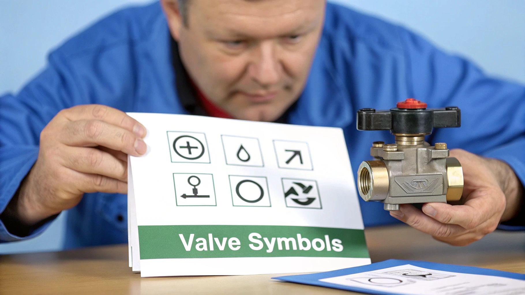
Interpreting Valve Symbols for Flow and Pressure Control
Valves are really the brains of a hydraulic system, dictating where the fluid goes, how much pressure it’s under, and how quickly it flows. If you can’t read the valve symbols on a circuit diagram, you’re flying blind. They might look a bit intimidating at first glance, but there’s a clear logic to them. Once you get the hang of it, schematics become much easier to understand.
The most common valves you’ll come across are directional control valves (DCVs). Their symbols are built around squares, which we often call ‘envelopes’. Each square represents one specific position the valve can shift into to redirect the fluid. So, a symbol with two squares is for a two-position valve; three squares mean it’s a three-position valve. Simple as that.
Look inside the squares, and you’ll see lines and arrows showing the available flow paths for that position. A ‘T’ symbol means that port is blocked. You’ll often see numbers like 4/3 or 4/2 used to describe a DCV. This is a shorthand for its key specs: the first number tells you how many ports (connection points) it has, and the second tells you the number of positions.
Decoding Actuation Methods
A valve symbol is only half the story without knowing how it’s operated. The small symbols tacked onto the ends of the main block show the actuation method, which is crucial for knowing how the system is actually controlled.
- Manual Control: Look for symbols like levers, push-buttons, or foot pedals. These indicate a person is directly operating the valve.
- Mechanical Control: A plunger or roller symbol means the valve is triggered by another mechanical part, like a cam.
- Solenoid Control: This is hugely common in modern electro-hydraulic systems. The symbol is a rectangle with a diagonal line through it, representing an electrical solenoid.
- Pilot Control: A dashed line leading to a small square tells you the valve is shifted using hydraulic pressure from a separate pilot line.
- Springs: The classic zigzag symbol represents a spring. Its job is usually to push the valve back to its starting position when the actuation force is removed.
Putting it all together, this combination of squares, flow paths, and actuators gives you a complete picture of the valve’s job. For instance, you can quickly spot a CETOP 3 directional valve on a schematic and know it’s solenoid-operated with a spring return, which is invaluable information for any technician.
Pressure and Flow Control Valves
Of course, hydraulics isn’t just about direction; it’s also about managing force and speed. This is where pressure and flow control valves come in, and their symbols are quite different from DCVs.
Pressure control valves are usually drawn as a single square containing an arrow, a spring, and a pilot line.
- A pressure relief valve is normally closed. Its symbol shows the arrow blocking the flow path. It only opens to divert fluid back to the tank when pressure (sensed by the pilot line) overcomes the spring’s force. For a deeper dive, check out our article on the function of a hydraulic pressure relief valve.
- A pressure reducing valve, on the other hand, is normally open. It works to maintain a steady, lower pressure downstream, no matter what’s happening upstream.
Flow control valves, often just called throttles, are all about regulating the speed of actuators like cylinders and motors. Their symbol is a simple restriction, and if there’s an angled arrow drawn across it, that means it’s adjustable. This allows an operator to fine-tune the flow and get precise control over movement.
Understanding Symbols for Actuators and Ancillary Components
If pumps create the flow and valves tell it where to go, then actuators are where the real work gets done. They’re the components that convert all that hydraulic energy back into mechanical force and motion. Of course, they don’t work in isolation. You also have a whole host of ancillary components, like filters and accumulators, that are absolutely vital for keeping the system healthy and running efficiently. For any MRO team, knowing the specific hydraulic circuit symbol for each of these is non-negotiable.
Actuators themselves fall into two main camps: linear (cylinders) and rotary (motors). The symbol for a hydraulic cylinder—the linear actuator—is a simple rectangle representing the cylinder barrel, with a T-shaped line inside for the piston and rod. The clever bit is how variations on this basic symbol tell you exactly how the cylinder functions.
Key Actuator Symbols
When you’re faced with a schematic, being able to correctly identify the type of cylinder is the first step in diagnosing common problems like cylinder drift or slow operation.
- Single-Acting Cylinder: This is the most basic type. It has just one fluid port, which pushes the piston out. You’ll spot it by the single connection point on the symbol. The return stroke isn’t powered by fluid; it relies on a spring (shown as a zigzag line inside the barrel) or simply the weight of the load itself.
- Double-Acting Cylinder: You’ll see this one everywhere. It has two ports, meaning fluid can be directed to either side of the piston. This gives you powered movement for both extension and retraction. The symbol makes this obvious with two connection points, one at each end of the rectangle.
- Cushioned Cylinder: To stop a piston from slamming into the end caps at high speed—a sure-fire way to cause damage—some cylinders have built-in cushioning. On a schematic, this is shown by a small rectangle added to the piston symbol, indicating controlled deceleration at the end of its travel.
Ancillary Component Symbols
These parts might not be in the spotlight, but a hydraulic system simply can’t function reliably without them. Their symbols are quite distinct and easy to spot once you know what you’re looking for.
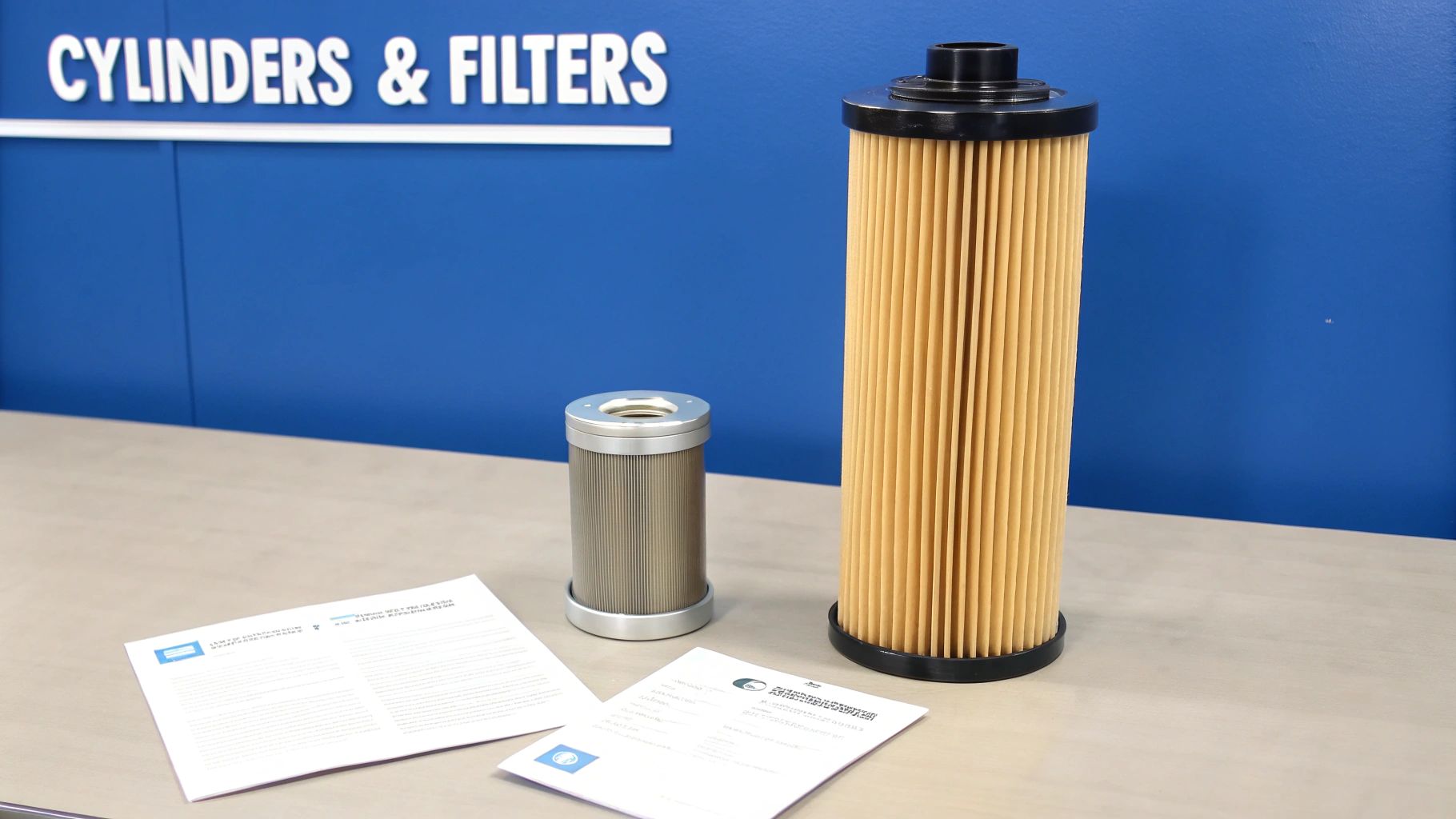
A filter is always represented by a diamond shape. Often, you’ll see a dashed line inside it, which represents the filter element. You’ll find this symbol dotted around the circuit diagram—on the return line, pressure line, or suction line—and it corresponds to the physical filters we supply, such as those from OMT.
An accumulator, which stores energy or damps pressure spikes, is drawn as an oval or circle split by a line. This line represents the bladder or diaphragm that separates the hydraulic fluid from the pressurised gas (usually nitrogen).
A manifold isn’t really a single symbol but is shown by how the various pathways are drawn. It’s depicted as a block with interconnected solid lines, illustrating how multiple valves and components are plumbed together in one compact unit.
The importance of reading these symbols correctly can’t be overstated. Back in the 1840s, William George Armstrong’s hydraulic crane—a true UK innovation—was depicted in early schematics with basic icons, laying the groundwork for the symbols we use today. More recently, a 2021 study by the UK Fluid Power Association found that a staggering 92% of failures in industrial hydraulics could be traced back to misinterpreting schematics. This highlights just how crucial it is to understand symbols for components like manifolds and clutches—the very core of the bespoke power packs up to 11 kW we build at MA Hydraulics. You can learn more about these findings on fluid power systems.
If you need a hand identifying a component from a schematic or you’re looking to source the right part for your system, give us a call on 01724 279508 or send us a message.
How to Read a Complete Hydraulic Circuit Diagram
Knowing the individual symbols is one thing, but the real skill lies in seeing how they all come together in a complete circuit. This is where you connect the dots, tracing the journey of the hydraulic fluid to understand the system’s logic. Think of a hydraulic schematic as a functional map—it shows what each component does and how it interacts with others, not where it physically sits.
To avoid getting lost, the trick is to read the diagram systematically. The best way I’ve found is to start at the power source and simply follow the flow. This logical approach helps you build a clear mental picture of how the system operates, which makes fault-finding or understanding the original design intent much easier.
A Step-by-Step Approach to Reading Schematics
I always tell people to think of reading a circuit diagram like reading a story. You start at the beginning (the reservoir), follow the main character (the fluid) on its journey, and watch how it interacts with the other characters (the components) before it finally returns home.
- Start at the Reservoir: First, find the symbol for the tank. This is ground zero—the starting and ending point for the hydraulic fluid.
- Find the Prime Mover and Pump: From the reservoir, trace the line to the pump, which will be connected to an electric motor or an engine. Look closely at the pump symbol. Is it fixed or variable displacement? This is a key detail.
- Follow the Pressure Line: The solid line coming out of the pump is your main pressure line. This is where the energised fluid flows to do the actual work. Keep an eye out for any pressure relief valves teed off this line; they’re the system’s primary safety device.
- Identify Control Valves: The pressure line will eventually lead you to a valve manifold or a set of directional control valves (DCVs). Analyse these symbols carefully to figure out how they direct the flow. Note their number of positions, ports, and how they’re operated (solenoid, lever, etc.).
- Locate the Actuators: Follow the lines from the valve’s work ports (often labelled A and B) out to the actuators, which could be a cylinder or a motor. This is the business end, where hydraulic energy becomes mechanical force.
- Trace the Return Path: Finally, follow the fluid’s path from the other side of the actuator, back through the control valve, and along the return line to the tank. You’ll often find filters on this return path, cleaning the oil before it starts its journey again.
The Importance of Standardised Symbols in Practice
Following this process really brings home why having a universal hydraulic circuit symbol standard is so vital. These symbols, governed by British Standards that align with ISO 1219-1 (adopted in the UK back in 1991), have massively improved safety and efficiency across the industry. In fact, standardisation has been shown to cut design errors in the nation’s hydraulic sector by up to 40%.
A 2022 survey by the British Fluid Power Association found that 85% of UK design engineers believe symbol standardisation has directly reduced schematic misinterpretation. This is absolutely critical for bespoke systems like the Hydronit mini power packs we assemble. For a deeper dive into how these standards are applied in practice, you can explore more about hydraulic symbology on Fluid Power World. You can also see how these components come together by reading our guide to the modern hydraulic power unit.
Common Symbols in a Basic Tipper Circuit
To see this in action, let’s break down a simple tipper circuit. It’s a great real-world example of how these symbols tell the story of a system.
| Hydraulic Circuit Symbol | Component Name | Function in Circuit |
|---|---|---|
| Reservoir (Tank) | Stores the hydraulic fluid. The starting and ending point for the fluid’s journey. | |
| Fixed Displacement Pump | Draws fluid from the reservoir and pushes it into the circuit to create flow. | |
| Pressure Relief Valve | Acts as a safety device, diverting excess flow back to the tank if pressure exceeds a set limit. | |
| 3/2 Directional Control Valve | Directs the flow of fluid to extend the cylinder or allows it to retract. | |
| Single-Acting Cylinder | The actuator that converts hydraulic pressure into linear force to lift the tipper body. |
As you can see, even in a basic setup, each symbol has a clear and distinct role. Once you learn the language, reading these diagrams becomes second nature.
If you’re working from a schematic and need a hand identifying or sourcing the right components, our expert team is always here to help. Just give us a call on 01724 279508, or send us a message with your requirements.
Your Expert Partner in Hydraulic Components
Getting to grips with hydraulic circuit symbols is absolutely fundamental for anyone working with fluid power systems in the UK. It’s the universal language we use, and fluency is crucial for keeping machinery safe, efficient, and reliable. Whether you're designing a new system from scratch, assembling it on the shop floor, or troubleshooting a breakdown under pressure, reading a schematic correctly is a non-negotiable skill.
Here at MA Hydraulics Ltd, we live and breathe this stuff. We know a schematic isn't just a collection of lines and boxes; it's the blueprint for your entire system. That's why we see our role as more than just a supplier. With decades of hands-on experience, our team is here to be your technical partner, helping you translate those symbols into real-world solutions and ensuring you get the right component for the job, first time.
Your One-Stop Hydraulic Solution
Whatever you're looking for, from a single replacement valve to a fully commissioned system, we have the inventory and the expertise to get you sorted.
- Extensive Component Range: We keep a huge stock of components from top-tier brands like Hydronit, Vivoil, and OMT, so you can count on quality parts delivered fast.
- Bespoke Power Packs: Our in-house engineers design and build custom industrial power packs up to 11 kW, built precisely to your requirements.
- Expert Technical Support: Stuck trying to decipher a symbol on an old diagram? Give us a call. We can help you cross-reference it and identify the exact part you need.
Don't let a confusing schematic bring your project to a standstill. For genuine expert advice, help with component selection, or to chat through the specifics of your next build, our team is always ready to help.
Give us a call on 01724 279508, or send us a message to get the support you need.
Your Hydraulic Symbol Questions Answered
When you're dealing with hydraulic systems, questions are bound to come up. It doesn't matter if you're a veteran engineer or a technician new to the trade; clear, straightforward answers are what you need to get the job done efficiently and safely. Here, we tackle some of the most frequently asked questions about hydraulic circuit symbols and how they apply in the real world.
Getting a solid grasp of these fundamentals is key. It helps you sidestep common mistakes, interpret schematics correctly, and ultimately leads to safer, more reliable systems. A good foundation in reading these diagrams is the first step in effective troubleshooting.
What Are the Four Basic Shapes in Hydraulic Schematics?
The visual language of hydraulics is built around four fundamental shapes, each defined by the ISO 1219-1 standard. Once you know these, you're on your way to deciphering any circuit diagram.
- Circle: This shape is all about energy conversion. It forms the basis for hydraulic pumps, which generate flow, and motors, which create rotary motion.
- Square: A square represents a directional control valve. You'll often see several squares linked together, with each one (or "envelope") showing a different path the fluid can take when the valve is shifted.
- Diamond: Think of this as a fluid conditioning unit. It's used for components like filters, coolers, and heaters – anything that keeps the hydraulic oil in good shape.
- Lines: These are your pipes and hoses. The style of the line tells you its purpose: a solid line is a main working line, a dashed line is a pilot line for control, and a dotted line typically indicates a drain.
How Do You Read Hydraulic Schematic Symbols?
Reading a schematic properly means looking at more than just the basic shapes; the real information is in the details inside them. A classic example is the small, solid triangle within a circle, which tells you the direction of energy or fluid flow.
If that triangle points outwards, you're looking at a hydraulic pump – it's pushing fluid out into the system. If it points inwards, it’s a hydraulic motor, which receives fluid to create mechanical force. Keep an eye out for other details, too, like a diagonal arrow drawn through a symbol, which tells you the component is variable (adjustable) rather than fixed.
What Is the Difference Between Connected and Crossing Lines?
Getting this right is absolutely critical, as it can completely change your understanding of a circuit. When you see two lines intersect on a schematic, you need to look closely for a connection node.
If there's a solid dot at the intersection, the lines are connected. Picture it as a 'T' fitting in the actual pipework. If the lines just cross over each other without a dot, they are not connected at all; one is simply passing over the other. Misinterpreting this is a very common and costly mistake.
Here at MA Hydraulics Ltd, we know that these schematics are the very blueprints of your machinery. If you're looking at a diagram and need a hand identifying or sourcing the right component, our expert team is ready to help.
Phone 01724 279508 today, or send us a message for technical support and fast component supply.
