A hydraulic pressure relief valve isn't just another part in your system; it's the critical safeguard that prevents catastrophic failures. Think of it as a safety net, constantly on watch, ready to automatically divert fluid flow the moment pressure climbs past a pre-set limit. Without it, you're risking equipment damage, costly downtime, and serious injury.
The Unseen Guardian of Your Hydraulic System
Every powerful hydraulic system, from a massive factory press in Sheffield to a hard-working tractor out in the Lincolnshire countryside, has an unsung hero working silently in the background. This is the hydraulic pressure relief valve, and its job is one of the most important for keeping the entire operation safe, reliable, and efficient.
Its purpose is actually quite simple, but absolutely vital. It works much like the steam whistle on an old-fashioned kettle, safely venting pressure before it builds to a dangerous, destructive level.
Without this crucial safeguard, a hydraulic system is essentially a ticking time bomb. A sudden pressure spike—maybe from a blocked line, an abrupt stop in an actuator's movement, or a control malfunction—can have disastrous results. The immense force of pressurised hydraulic fluid can burst hoses, crack manifolds, wreck expensive pumps and motors, or even bend and break solid steel components.
The Real Cost of Neglect
The fallout from a missing or faulty relief valve goes well beyond just a broken part. The consequences can be severe and ripple across the entire operation, hitting both your budget and your team's safety.
- Expensive Downtime: When a system fails, everything grinds to a halt. Every minute that machinery is offline is a minute of lost productivity and revenue.
- Catastrophic Equipment Damage: The cost to repair or replace major components like pumps, cylinders, or motors can easily run into thousands of pounds, and that's before you even factor in labour.
- Serious Safety Hazards: A high-pressure jet of hydraulic fluid from a burst hose can cause life-changing injection injuries, while the sudden failure of a mechanical part puts anyone nearby in grave danger.
This is precisely why this one component is non-negotiable for any industrial or mobile hydraulic system. Its presence is a hallmark of professional, safety-conscious engineering. The growing importance of these valves is reflected in market trends across the UK, where the pressure relief valve market is seeing a steady 5.0% CAGR. This growth is fuelled by tightening safety regulations and the modernisation of critical sectors like offshore oil platforms, where advanced hydraulic relief valves are essential for handling pressures up to 20 bar. You can find out more about the critical role of these components from detailed industry market analysis.
Core Functions at a Glance
To really get a handle on why these valves are so important, it helps to break down their main jobs. The table below gives a quick summary of what they do and why it matters.
Table: Core Functions of a Hydraulic Pressure Relief Valve
| Function | Description | Benefit to System |
|---|---|---|
| Pressure Limitation | Sets the maximum allowable pressure in the circuit or a specific sub-circuit. | Stops components from being stressed beyond their design limits, preventing premature wear and failure. |
| System Protection | Vents excess flow back to the tank during a pressure spike or overload condition. | Protects pumps, actuators, hoses, and fittings from the damaging effects of over-pressurisation. |
| Safety Assurance | Acts as the primary failsafe against uncontrolled pressure build-up. | Shields operators and other personnel from high-pressure fluid leaks and sudden mechanical failures. |
At the end of the day, a correctly specified and properly installed hydraulic pressure relief valve is your first and best line of defence, ensuring your machinery can operate safely and reliably, day in and day out.
For expert advice on choosing the right valve for your system, give us a call on 01724 279508 today, or send us a message through our website.
How Different Types of Relief Valves Work
While every hydraulic pressure relief valve has the same core job—to stop a system from over-pressurising—they don’t all go about it in the same way. The mechanics inside the valve body can be quite different, which in turn affects how they perform. Getting to grips with these differences is the key to picking the right valve for the job.
Broadly speaking, the world of relief valves is split into two main camps: the straightforward direct-acting valve and the more sophisticated pilot-operated valve. Each has its own set of strengths and is built for different kinds of operational demands.
The Simplicity of Direct-Acting Valves
Think of a simple gate held shut by a spring. That's the essence of a direct-acting relief valve. It's the most basic design, relying on a simple balance of mechanical forces to do its job.
Inside, a spring pushes a poppet or ball directly against a seat, blocking the flow of hydraulic fluid. As long as the system pressure stays below the force exerted by the spring, the valve stays shut and the system runs as normal.
But when the pressure in the system climbs high enough to overcome the spring's pre-set tension, it forces the poppet or ball off its seat. This opens up a path for the excess fluid to escape to the reservoir, instantly dropping the pressure in the main circuit. Its reaction time is incredibly quick, making it a fantastic choice for protecting systems from sudden, sharp pressure spikes.
Thanks to their simple design, direct-acting valves tend to be:
- Cost-Effective: With fewer moving parts, they're cheaper to make. A standard, small direct-acting valve might only set you back £30-£60.
- Compact: Their uncomplicated construction means they take up less space.
- Fast-Responding: They react almost immediately when pressure gets too high.
This concept map gives a great visual breakdown of the crucial protective functions a relief valve provides.
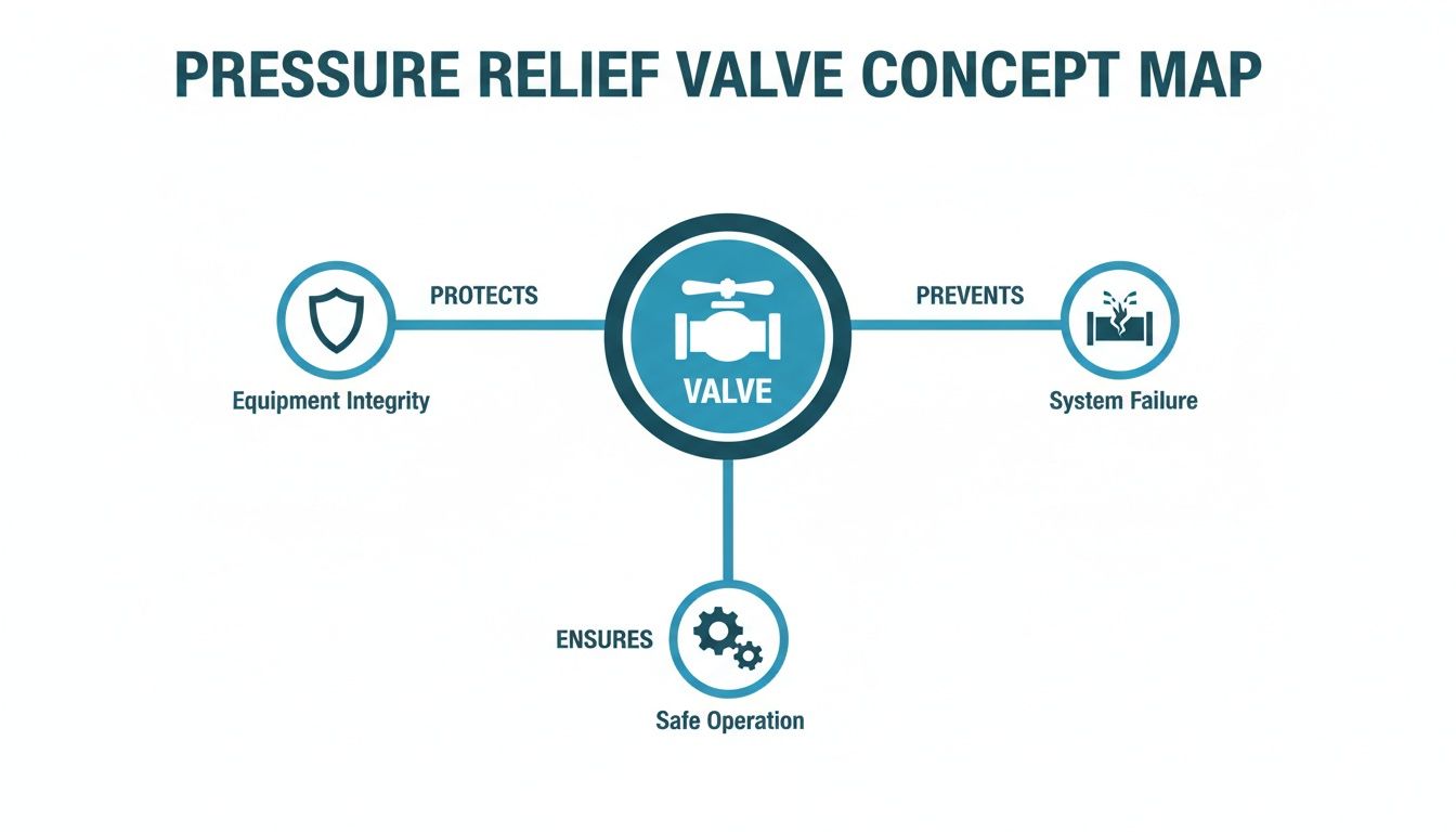
As you can see, the valve’s role is really threefold: it protects individual components, prevents catastrophic system failure, and ensures everything operates safely and consistently.
The Precision of Pilot-Operated Valves
Now, let's look at a more advanced design. A pilot-operated relief valve is like having a small, sensitive lookout who controls a much larger, stronger gatekeeper. It’s a two-stage valve, engineered for systems that need to handle higher pressures and larger flow rates with much more stability.
This design has a small pilot valve (which is often a direct-acting valve itself) that controls the main, larger valve spool. Under normal pressure, the main spool is held closed by a light spring and the system's own hydraulic pressure.
When the system pressure rises to the pilot valve's setting, this small valve opens first. This vents a tiny amount of fluid from behind the main spool, which creates a pressure imbalance. That imbalance is what causes the large main spool to shift, opening a much wider path for the main flow to be relieved back to the tank.
The real advantage here is stability. Because the main valve is hydraulically balanced, it operates incredibly smoothly. It's far less prone to the instability or 'chatter' that can sometimes plague direct-acting valves when they're operating near their set pressure, especially with high flow rates.
This two-stage action brings a few key benefits:
- High Flow Capacity: It can manage much higher volumes of fluid than a direct-acting valve of a similar size.
- Excellent Stability: The design minimises pressure override—the gap between the pressure at which the valve cracks open and the pressure at which it's fully flowing.
- Remote Control Capability: Many designs allow the pilot stage to be controlled from elsewhere, giving engineers much more flexibility in their system design.
To help you decide, here’s a quick comparison of the two main types.
Direct-Acting vs Pilot-Operated Relief Valves
| Feature | Direct-Acting Relief Valve | Pilot-Operated Relief Valve |
|---|---|---|
| Operation | Single-stage; spring directly opposes system pressure. | Two-stage; a small pilot valve controls a larger main spool. |
| Response Time | Very fast, almost instantaneous. | Slightly slower due to the two-stage action. |
| Flow Capacity | Best for lower flow rates. | Excellent for high flow rates. |
| Pressure Stability | Can be prone to chatter near set pressure. | Very stable, with minimal pressure override. |
| Complexity & Cost | Simple, reliable, and lower cost. | More complex and generally more expensive. |
| Typical Use | Protecting against sudden pressure spikes, small circuits. | Large industrial machinery, main system relief, precision control. |
Ultimately, the choice comes down to your system’s specific needs. A direct-acting valve is a robust, fast, and economical solution for many applications, whereas a pilot-operated valve offers the precision and stability required for more demanding, high-flow industrial systems.
These characteristics make pilot-operated valves perfect for heavy-duty industrial machinery, like large presses or injection moulding machines, where precise pressure control is absolutely critical. For a closer look at the technical details, you can browse the specifications in our technical datasheets for LUEN cartridge valves, which include many pilot-operated options.
Give us a call on 01724 279508 today, or send us a message to chat about which valve type is the right fit for your application.
Selecting and Sizing Your Relief Valve Correctly
Choosing the right hydraulic pressure relief valve isn’t just about picking a part from a catalogue. It’s a critical engineering decision that has a direct impact on your machine’s safety, performance, and lifespan. Get it wrong, and you could be facing dangerous pressure spikes, sluggish performance, or constant, frustrating system instability.
Let’s walk through the essentials to make sure you get it right the first time.
Nailing the selection means your system will be both safe and efficient. A valve that’s too small simply can’t handle the pump’s full flow, which leads to excessive pressure and heat build-up. Go too big, however, and the valve can become unstable at lower flow rates, causing that tell-tale ‘chatter’ that signals a serious problem.
Key Sizing Parameters
To choose the right valve, you absolutely must have three core pieces of information about your hydraulic system. These aren’t suggestions; they’re the non-negotiable data points that will guide your entire decision.
- Maximum System Operating Pressure: This is the highest pressure your system is designed to hit during a normal work cycle. Your relief valve needs to be set slightly above this—typically by 10-15%. This stops it from opening unnecessarily but ensures it triggers before damaging the system’s weakest component.
- Maximum Pump Flow Rate: You need to know the pump’s maximum output in litres per minute (LPM). The relief valve has to be rated to handle this full flow, otherwise, it can’t divert all the fluid back to the tank when a pressure spike occurs.
- Required ‘Cracking’ and ‘Full-Flow’ Pressure: These two figures are crucial. ‘Cracking pressure’ is the point where the valve first starts to open. ‘Full-flow pressure’ is the higher pressure at which the valve is passing the pump’s entire output. The gap between them is called pressure override, and understanding it is vital for stable performance.
Beyond Pressure and Flow
While pressure and flow are the headline figures, a few other factors are just as important for ensuring the valve you choose will work reliably for years to come.
- Fluid Compatibility: The valve’s internal seals and body must be compatible with your hydraulic fluid. Whether you’re using standard mineral oil, a biodegradable fluid, or a fire-resistant type, a mismatch can destroy seals and cause premature failure.
- Operating Temperature: Think about both the workshop or field temperature and the fluid’s own operating temperature. Drastic temperature swings can affect a valve’s performance, so make sure your choice is rated for your system’s expected range.
- Port Sizing and Type: The valve’s port connections must match your system’s pipework. It’s tempting to use adaptors to make an incorrectly sized valve fit, but this can create flow restrictions and pressure drops you really don’t need.
For a detailed look at specific models and their specifications, you can explore our range of high-quality OMT Group inline relief valves to find a suitable match for your requirements.
Real-World Sizing Examples
Let’s ground this with a couple of practical scenarios you might encounter.
Example 1: A Farm Tractor Auxiliary Circuit
Picture this: you’re adding a hydraulic log splitter to a compact tractor. The tractor’s auxiliary pump puts out 25 LPM at a maximum system pressure of 170 bar.
You’d start by looking for a valve that can handle at least 25 LPM. To protect the system, you’d set the cracking pressure around 185 bar (roughly 10% above the max operating pressure). A simple, direct-acting inline relief valve, likely costing between £40 and £70, is the perfect and most cost-effective solution here.
Example 2: A Factory Stamping Press
Now, let’s switch to a large industrial press. Its hydraulic power unit delivers a hefty 200 LPM at a working pressure of 250 bar.
This high-flow, high-pressure system demands a much more stable solution. A direct-acting valve would almost certainly chatter and perform erratically. The right choice is a pilot-operated relief valve rated for well over 200 LPM. Its two-stage design provides the smooth, stable pressure control needed to safeguard a machine that could be worth tens of thousands of pounds.
Making an informed choice based on these factors ensures your hydraulic pressure relief valve will perform its guardian role perfectly.
For help selecting the right components, phone 01724 279508 today, or send us a message to discuss your specific application.
A Practical Guide to Installation and Adjustment
Picking the right hydraulic pressure relief valve is only half the job. Honestly, its real-world performance comes down to proper installation and careful adjustment. You could have the best valve on the market, but if it’s not fitted correctly, it won’t protect your system. For any maintenance engineer or MRO team, getting this part right is absolutely fundamental to system safety and efficiency.
It all starts with the basics. Before you do anything else, make sure the valve is clean and free from any gunk it might have picked up in storage. Even a tiny bit of debris can stop the poppet from seating properly, which leads to annoying leaks and unreliable pressure control.
Next, and this is a big one, take a moment to check the valve’s ports. Most will have an inlet marked ‘P’ (for pressure) and a tank or exhaust port marked ‘T’ (for tank). Getting these mixed up is a surprisingly common, and very serious, mistake. If you connect the pressure line to the tank port, the valve is useless, leaving your system with zero protection against a pressure spike.
Preparing for a Secure Installation
With the valve clean and the ports identified, the next step is mounting it securely and in the right orientation. The way it’s positioned can actually affect how it works, especially with simpler direct-acting designs where gravity can play a part. Your first port of call should always be the manufacturer’s datasheet for any specific mounting instructions.
For a solid, leak-free installation, stick to these key steps:
- Connect the Ports Correctly: Double-check that the high-pressure line from the pump goes to the ‘P’ port. The line heading back to the hydraulic reservoir must connect to the ‘T’ port.
- Use the Right Fittings: Make sure you’re using the correct size and type of hydraulic fittings (like BSPP or JIC) to match the valve. Using the wrong threads is a guaranteed way to get leaks and can even damage the valve body itself.
- Don’t Over-Tighten: It’s tempting to really crank down on the fittings, but this is a classic mistake. Over-tightening can warp the valve body, causing the internal parts to stick or jam. Use a torque wrench and stick to the manufacturer’s recommended settings to get a good seal without causing damage.
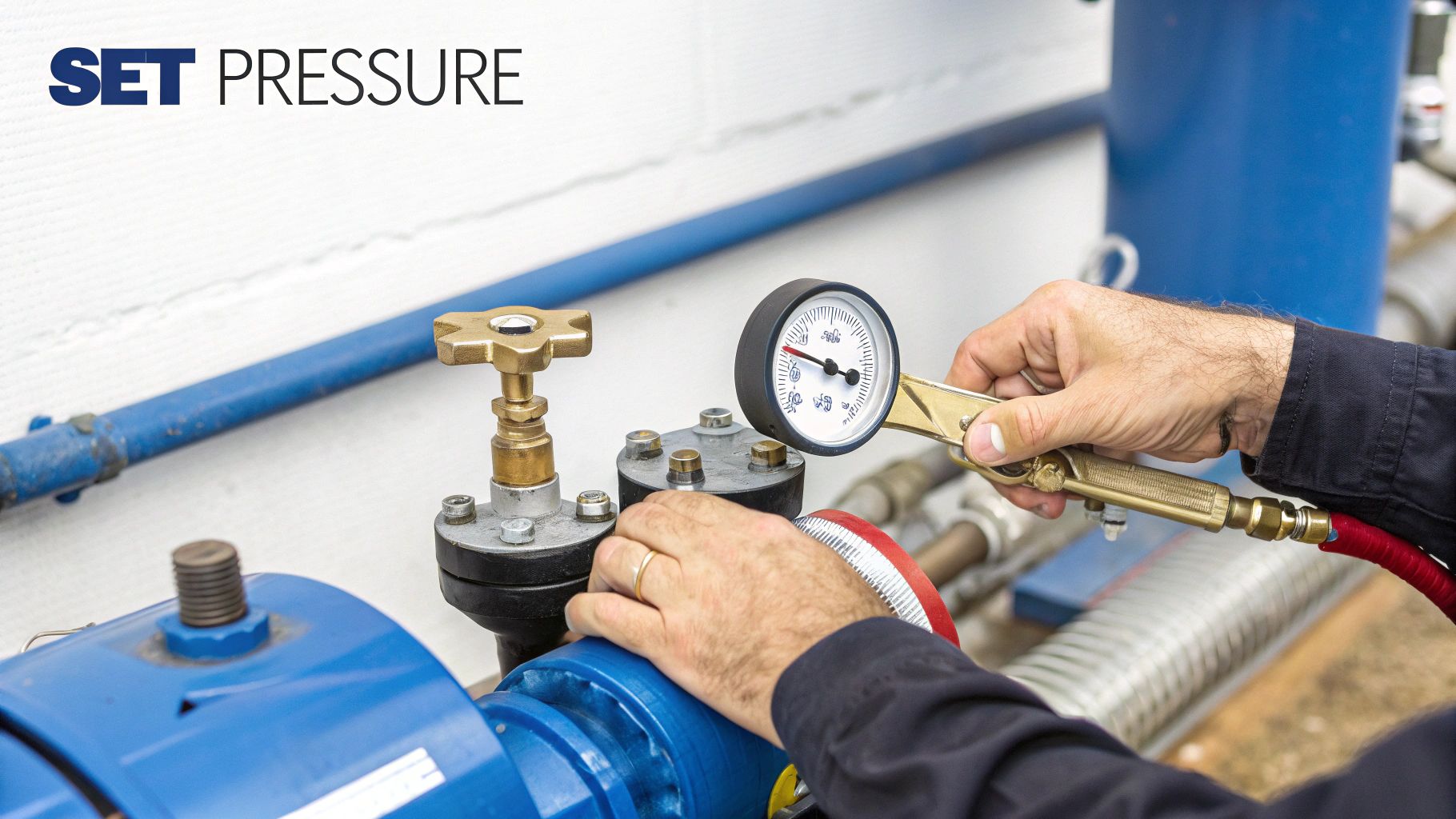
Setting the Pressure Correctly and Safely
Once the valve is installed, it’s time for the most critical part: setting the pressure. You have to do this with the system running, and you’ll need a properly calibrated pressure gauge to get it right. The gauge should be fitted somewhere in the pressure line, usually between the pump and the relief valve, so you can see exactly what’s happening.
Safety First: Here’s the golden rule of pressure setting: never set the relief valve higher than the maximum pressure rating of the weakest component in your circuit. That includes everything—hoses, cylinders, motors, and fittings. Pushing past that limit puts the entire system, and anyone working nearby, in danger.
Follow this straightforward process to set your pressure safely:
- Start Low: Before you fire up the system, turn the valve’s adjustment screw or knob anti-clockwise all the way out. This backs it off to its lowest pressure setting and prevents any nasty surprises when you start the pump.
- Activate the System: Turn on the hydraulic power pack or engine. With the valve backed off, the fluid should just be circulating back to the tank with very little resistance.
- Create a Dead-End: To set the valve, you need to block the flow downstream. The easiest way is to use a directional control valve to run a cylinder to its end-of-stroke or simply use a shut-off valve.
- Adjust Gradually: Slowly turn the adjustment screw clockwise while keeping a close eye on the pressure gauge. You’ll see the pressure start to climb. Keep making small, steady turns until the gauge hits your target maximum system pressure.
- Lock it In: Once you’ve nailed the setting, tighten the lock nut on the adjustment screw. This stops it from vibrating loose during operation and undoing all your hard work.
For a closer look at a specific setup, we have a detailed guide that explains how to adjust the relief valve on a Vivoil flow divider. By following these steps with care, you can be confident your pressure relief valve will do its job and act as the reliable guardian it was designed to be.
Our expert team is here to help. Give us a call on 01724 279508 today, or send us a message to talk through your requirements.
Troubleshooting Common Relief Valve Problems
Even the best-built hydraulic pressure relief valve will need a bit of attention eventually. Like any component that’s constantly at work, it’s going to face wear, contamination, and the general stress of day-to-day operation. If you get ahead of potential trouble and know what to look for, you can stop small hitches from spiralling into a full-blown system failure.
Think of this as a practical field guide for MRO teams and service engineers. It’s all about spotting the signs and knowing how to fix the common headaches. A little preventative maintenance goes an incredibly long way, slashing the risk of sudden downtime and eye-watering repair bills.
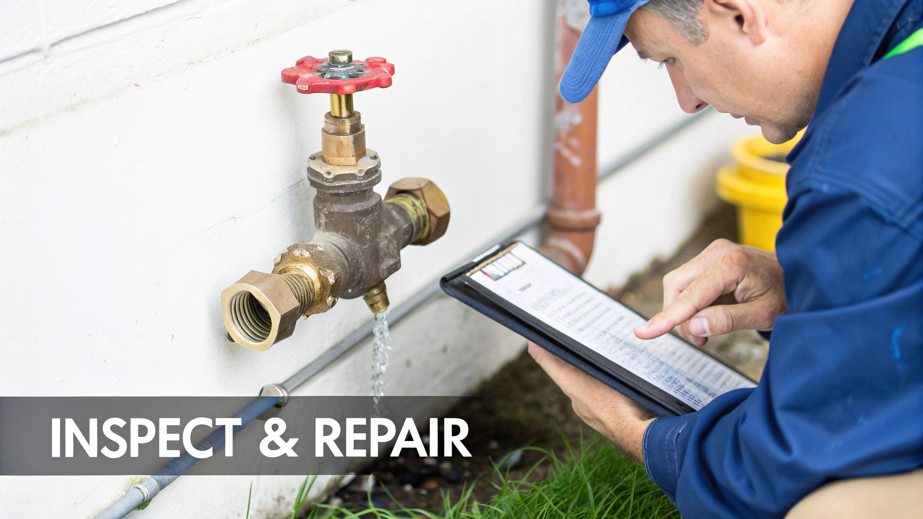
Building a Routine Maintenance Schedule
A solid maintenance routine is the bedrock of any reliable hydraulic system. It doesn’t have to be over-the-top, but it absolutely must be consistent. Weaving these simple checks into your regular machine inspections will pay you back tenfold.
- Weekly Visual Checks: Have a quick look for any external leaks around the valve body, fittings, and the adjustment screw. A clean valve is usually a happy valve; if it’s caked in grime, it’s probably hiding a slow leak that’s only going to get worse.
- Monthly Pressure Verification: If the system has a pressure gauge, glance at it to make sure the relief pressure hasn’t wandered off its setting. Any drift could point to a weakening spring or some gunk building up inside.
- Quarterly Fluid Analysis: Dirty hydraulic fluid is public enemy number one for every component in the system. Taking regular oil samples to check for water, grit, or tiny metal particles will tell you if there’s trouble brewing. Contaminants are notorious for clogging small passages and causing valve parts to stick or wear out fast.
Common Problems and How to Fix Them
When a relief valve starts playing up, the symptoms themselves often give you the biggest clues. The trick is to think through the possibilities logically, starting with the easiest and most common culprits first.
Before you condemn the valve, hold on. More often than not, the real issue is the system’s condition—usually contaminated fluid or a setting that’s drifted out of spec. A methodical approach saves time, money, and stops you from replacing perfectly good parts.
Here’s a no-nonsense chart to help you track down and sort out the most frequent issues you’re likely to run into.
| Problem | Likely Causes | Actionable Solutions |
|---|---|---|
| Pressure Chatter or Squealing | 1. Incorrect Sizing: The valve is simply too big for the system’s flow rate. 2. Low Viscosity: The oil is too thin, which is often a sign of overheating. 3. Worn Poppet/Seat: The internal sealing surfaces are damaged, so the valve can’t operate smoothly. | 1. Verify Sizing: Match the valve’s flow rating to the pump’s output. If it’s wrong, it needs replacing. 2. Check Fluid & Temp: Make sure you’re using the right grade of oil and the system cooler is actually working. 3. Inspect/Replace Valve: If the oil and sizing check out, the valve itself is probably worn and ready for replacement. |
| Valve Fails to Reseat (Constant Leak) | 1. Contamination: A tiny piece of debris is wedged between the poppet and its seat, holding it open. 2. Broken Spring: The internal spring has snapped and can no longer push the valve closed. 3. Damaged Seat: The valve seat has a score or pit in it, wrecking the seal. | 1. Flush the System: Cycling the valve under pressure can sometimes clear the blockage. If that fails, the oil needs filtering or changing. 2. Replace the Valve: A broken spring is a fatal flaw. The whole valve needs to be replaced. 3. Inspect and Replace: Just like with a broken spring, a damaged seat means it’s time for a new valve. |
| Premature Opening (Low Pressure) | 1. Incorrect Adjustment: The pressure setting has crept down over time or was never set right in the first place. 2. Weakened Spring: After thousands of cycles, the spring has simply lost its strength. 3. Internal Leakage (Pilot-Operated): On these more complex valves, a leak in the pilot section can trick the main stage into opening early. | 1. Re-adjust Pressure: Use a calibrated gauge to set the valve back to the correct system pressure. 2. Replace the Valve: A weak spring means the valve has come to the end of its useful life. 3. Inspect/Replace Valve: Internal wear in a pilot-operated valve generally means replacement is the safest and most reliable fix. |
By working through problems this way, your team can get things sorted quickly and keep your machinery earning its keep.
How Relief Valves Power UK Industry and Mobile Machinery
The theory behind hydraulic pressure relief valves really comes to life when you see them at work. Across the UK, these components are the unsung heroes in countless machines, quietly ensuring safety and precision in some of our most vital industries. From sprawling factories to muddy farm fields, they’re absolutely essential.
Seeing them in action shows how a technical detail translates directly into operational reliability and, ultimately, profit. A properly selected valve isn’t just another part; it’s the bedrock of predictable, safe performance.
Protecting Precision in Industrial Settings
In UK manufacturing, precision and safety are everything. Think of the immense force of a hydraulic press stamping out metal parts, or an injection moulding machine creating complex plastic components. Both rely on incredibly stable pressure control to get the job done right.
This is where a pilot-operated hydraulic pressure relief valve often shines. It doesn’t just protect multi-million-pound machinery from damaging pressure spikes; it ensures the exact same force is applied, cycle after cycle. That level of consistency is crucial for quality control and keeping scrap rates down.
You’ll also find them protecting the bespoke hydraulic power packs that drive automated production lines in factories from Coventry to Cardiff. Here, they act as a critical safeguard, preventing catastrophic failures that could shut down a whole operation for days.
A single pressure spike in an automated manufacturing line can cause a domino effect, damaging not just the hydraulic system but also expensive tooling and robotics. The relief valve acts as the primary circuit breaker, isolating the problem before it escalates.
Safeguarding Mobile Machinery in the Field
The world of mobile machinery is tough and unpredictable. Agricultural and construction equipment regularly face sudden, jarring shock loads that send destructive pressure waves hammering through a hydraulic system.
Picture a couple of common scenarios:
- Agricultural Machinery: A combine harvester’s header hits a hidden boulder, or a tractor’s front loader slams into the ground. A direct-acting relief valve reacts in a split second, venting that pressure spike before it can blow a hose or damage a cylinder, often miles from the nearest workshop.
- Construction Equipment: An excavator digging through tough ground or a crane lifting a heavy, awkward load sees constant fluctuations in hydraulic pressure. The relief valve is there to make sure that as rams bottom out or the machine hits unexpected resistance, the pressure stays within safe limits, protecting both the operator and the equipment.
In these situations, the valve isn’t a complex control component; it’s a rugged, reliable bodyguard against the harsh realities of working on-site.
Driving Innovation in New Sectors
The role of the hydraulic pressure relief valve is also expanding into highly specialised fields. For instance, the UK’s pharmaceutical sector has seen a remarkable adoption of these components. A major biomanufacturing plant that recently opened in Scotland integrated advanced valve systems to maintain sterile processing conditions under varying hydraulic pressures. This single project required thousands of units set for pressures up to 20 bar, highlighting a significant year-on-year increase in their use for biopharma applications. Regulatory updates have spurred investments exceeding £500 million in high-performance relief solutions across the UK. You can find more insights in this report on the growing pressure relief valve market.
For expert guidance on selecting the perfect valve for your industrial or mobile application, give us a call on 01724 279508 today, or send us a message to discuss your requirements.
Getting It Right: Your Partner in Hydraulic System Safety
When you get down to it, a pressure relief valve isn’t just another part in the system; it’s the essential safety net. Think of it as the guardian standing watch over your entire hydraulic circuit, preventing the dangerous pressure spikes that can lead to catastrophic failures.
Getting the selection, installation, and maintenance right isn’t just a box-ticking exercise. It’s fundamental to keeping your machinery safe, efficient, and running for the long haul. A correctly specified and maintained valve means less downtime, fewer costly repairs, and a much safer working environment for everyone.
At MA Hydraulics, we’ve spent decades living and breathing this stuff. We’ve seen firsthand what works and what doesn’t, which is why we partner with trusted, industry-leading brands like Vivoil and Hydronit. We’re here to help you find the right high-quality components for whatever you’re building or maintaining.
We’re Here to Help
Whether you’re an OEM engineer wrestling with a new design or an MRO technician who needs a reliable replacement part yesterday, our team is ready to jump in. We get the real-world pressures you’re under and have the technical know-how to guide you to the right solution.
Our goal is simple: to help you build safer, more productive, and more dependable hydraulic systems. We provide the components and the practical advice you need to protect your investment and keep things running smoothly.
For expert advice and access to a huge range of hydraulic components, you can count on MA Hydraulics Ltd.
Phone 01724 279508 today, or send us a message to talk through your requirements.
